Vehicle steering control device and method

a steering control and vehicle technology, applied in the direction of steering initiation, vessel construction, instruments, etc., can solve the problem that the steering wheel always receives a road-surface reaction force which is generated

Inactive Publication Date: 2010-06-03
NISSAN MOTOR CO LTD
View PDF4 Cites 27 Cited by
  • Summary
  • Abstract
  • Description
  • Claims
  • Application Information

AI Technical Summary

Benefits of technology

[0005]By focusing on the above-mentioned problem, it is an object of the present invention to provide a steering control device or method for a vehicle, devised to be capable of preventing the driver from feeling the restraint on the steering wheel during the automatic turning control.

Problems solved by technology

However, in the above-mentioned earlier technology, the steering wheel always receives a road-surface reaction force which is generated.
There has been such a problem in the earlier technology.

Method used


Image

  • Vehicle steering control device and method
  • Vehicle steering control device and method
  • Vehicle steering control device and method

Examples


first embodiment

[0027]At first, a configuration will now be explained.

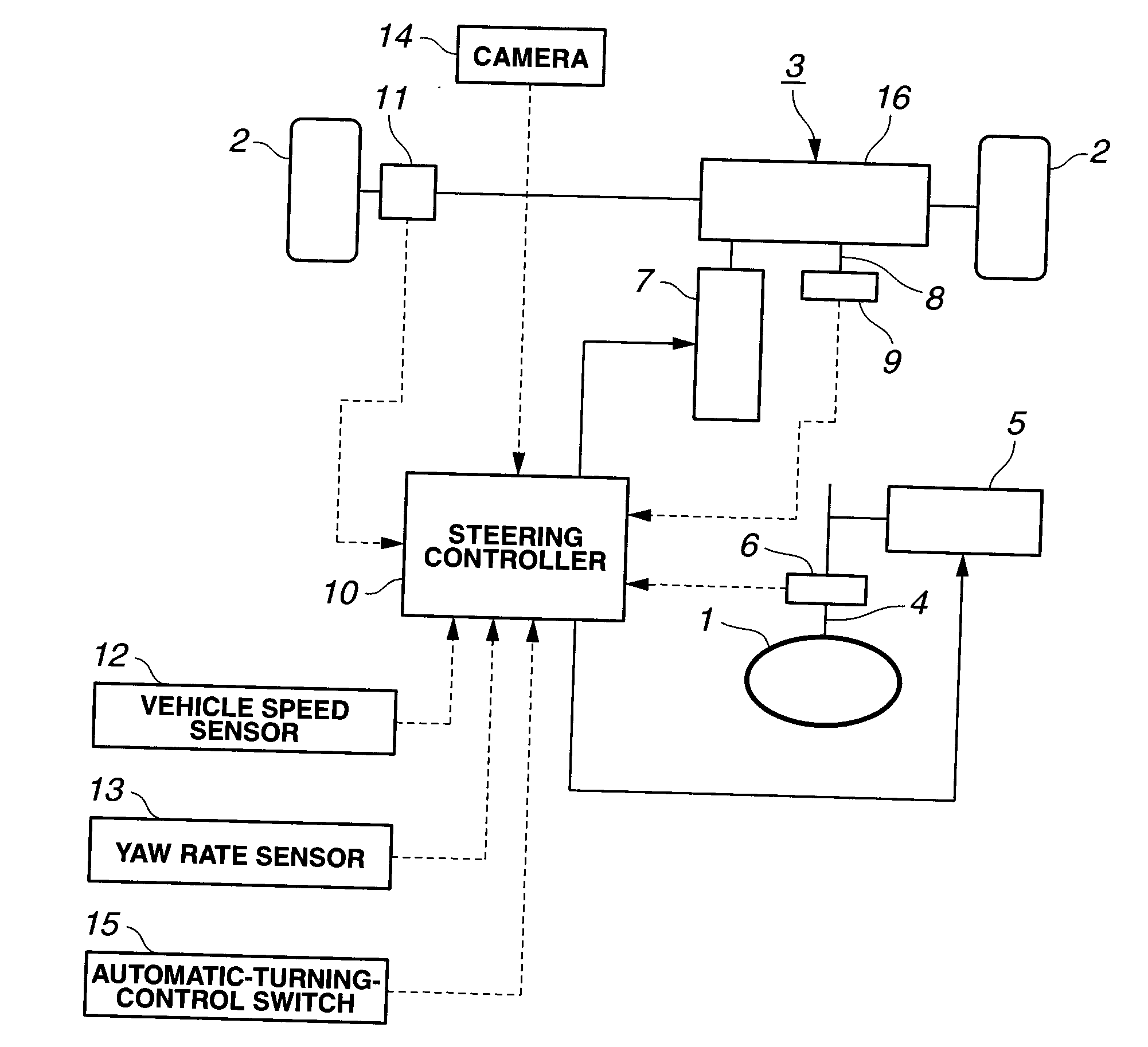
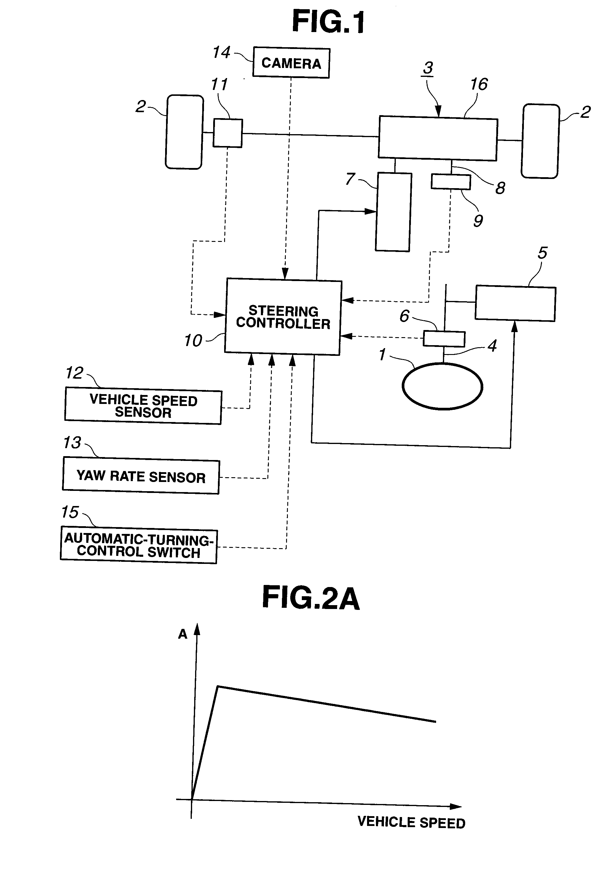
[0028]FIG. 1 is a schematic configuration view of a steer-by-wire system to which a vehicle steering control device of a first embodiment according to the present invention has been applied. That is, the vehicle steering control device in the first embodiment is a so-called steer-by-wire (SBW) system in which a steering wheel 1 is mechanically disconnected or detached from a turning mechanism 3 for tuning front road-wheels (steering road-wheels) 2, 2.

[0029]A column shaft 4 supporting the steering wheel 1 is provided with a reaction-force motor (reaction-force mechanism) 5 and a steering angle sensor 6. The reaction-force motor 5 functions to apply a steering reaction force to the steering wheel 1. The steering angle sensor 6 functions to detect a rotation angle of the column shaft 4, as a steering angle which is a rotation angle of steering wheel 1 relative to a straight running state. The turning mechanism 3 is provided with a t...

second embodiment

[0089]In a second embodiment according to the present invention, the steering reaction force is produced according to the target turning angle.

[0090]A schematic configuration of the second embodiment is similar as that of the first embodiment shown in FIG. 1. Hence, explanations and diagrammatic representations thereof will be omitted.

[0091]FIG. 11 is a control block diagram of a steering controller 10 in the second embodiment. In the second embodiment, there is provided an offset angle calculating section 10g instead of the turning reaction-force correcting section 10f of the first embodiment shown in FIG. 3.

[0092]A steering-reaction-force calculating section 10c in the second embodiment calculates the target steering reaction force by use of the following formula when the absolute value of target deviation angle calculated by the automatic turning calculating section 10d is greater than the value |α|.

Target Steering Reaction Force=−S×Third Target Turning Angle

[0093]Wherein the thi...

third embodiment

[0105]In a third embodiment according to the present invention, a variation of the turning reaction force which has a frequency greater than or equal to a predetermined frequency value is reflected to the steering reaction force. A schematic configuration of the third embodiment is similar as that of the first embodiment shown in FIG. 1. Hence, explanations and diagrammatic representations thereof will be omitted.

[0106]FIG. 14 is a control block diagram of a steering controller 10 in the third embodiment. In the third embodiment, there is provided a rack axial-force sensor 11 and a high-pass filter 10i in addition to the configuration of the second embodiment shown in FIG. 11.

[0107]In the third embodiment, the turning reaction force derived from the rack axial-force sensor 11 is inputted through the high-pass filter 10i to a steering-reaction-force calculating section 10c. This high-pass filter 10i passes a component of the turning reaction force which is higher than the predetermin...


PUM


Abstract

Under an automatic turning control, a steering controller defines a value of steering angle set according to a target turning angle of the automatic turning control, as a value of steering angle at which a reaction force is equal to 0. Thereby, the steering controller controls a steering reaction force on the basis of a difference between an actual steering angle and the value of steering angle at which the reaction force is equal to 0.

Description

TECHNICAL FIELD[0001]The present invention relates to a vehicle steering control device having an automatic turning control function.BACKGROUND ART[0002]When an automatic turning control for automatically controlling a turning angle of a steering road-wheel(s) irrespective of an operation of a steering wheel, e.g. a lane keeping control, is performed, a steering angle is set in dependence upon the turning angle of the steering road-wheel in a vehicle steering control device of earlier technology (for example, see the following Patent Document 1). Thereby, a mismatch between the steering angle and a vehicle behavior is avoided to suppress uncomfortable feeling which is given to a driver.[0003]Patent Document 1: Japanese Patent Application Publication No. 2006-264374SUMMARY OF THE INVENTION[0004]However, in the above-mentioned earlier technology, the steering wheel always receives a road-surface reaction force which is generated. At the same time, the steering wheel always receives a ...

Claims


Application Information

Patent Timeline
Patent Type & Authority Applications(United States)
IPC IPC(8): G06F19/00B62D5/04B62D6/00B62D101/00B62D111/00B62D113/00B62D121/00
CPCB62D6/002B62D15/025B62D6/008B62D6/003
Inventor SUZUKI, TAKUEGUCHI, TAKAAKICHAI, YUWUNYOSHIZAWA, HIROYUKINISHIDA, YUKINORI
Owner NISSAN MOTOR CO LTD
Why Eureka
Try Eureka