

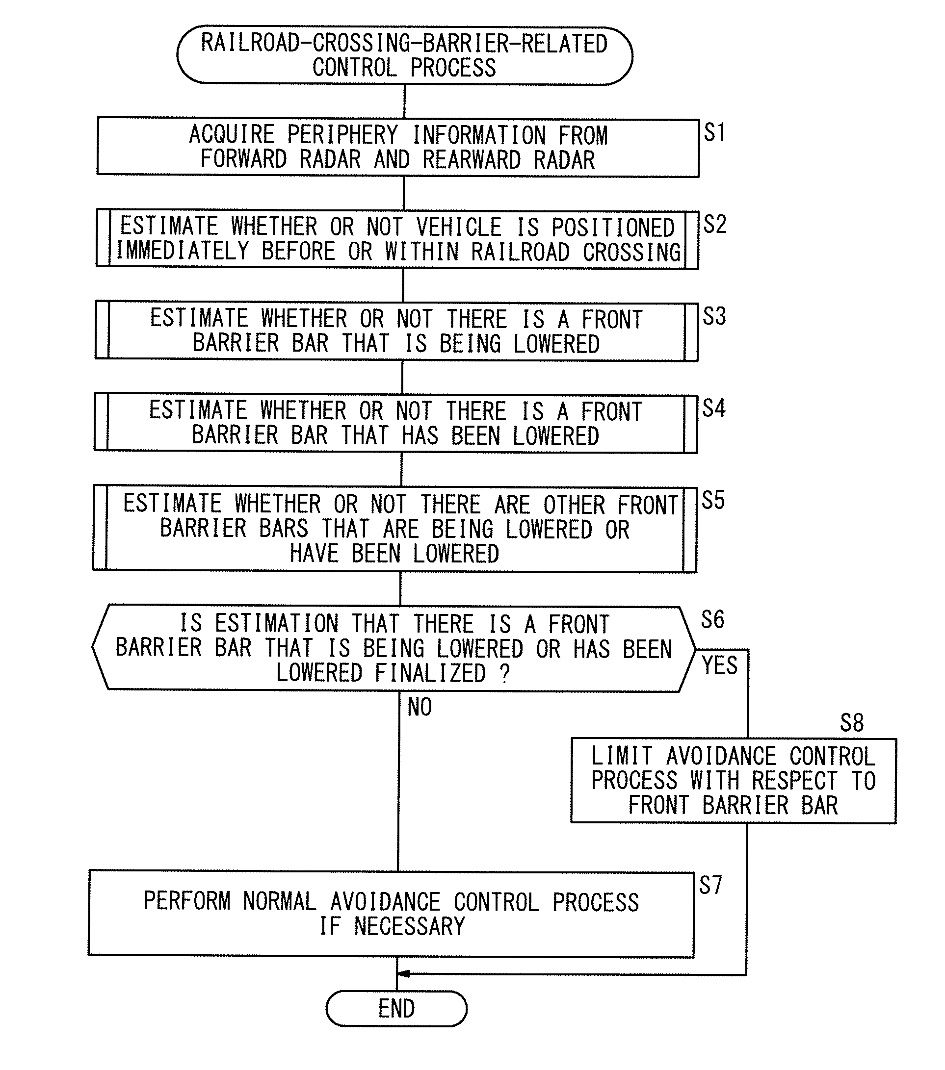
Railroad crossing barrier estimating apparatus and vehicle
a technology for estimating apparatus and railroad crossing, which is applied in the direction of scene recognition, instruments, and reradiation, etc., can solve the problems of limiting the vehicle speed of the host vehicle, driver may feel strange or awkward, so as to increase the accuracy of judgment about the railroad crossing barrier
- Summary
- Abstract
- Description
- Claims
- Application Information
AI Technical Summary
Benefits of technology
Problems solved by technology
Method used
Image

Examples
first embodiment
A. First Embodiment
1. Configuration
(1-1. Overall Configuration)
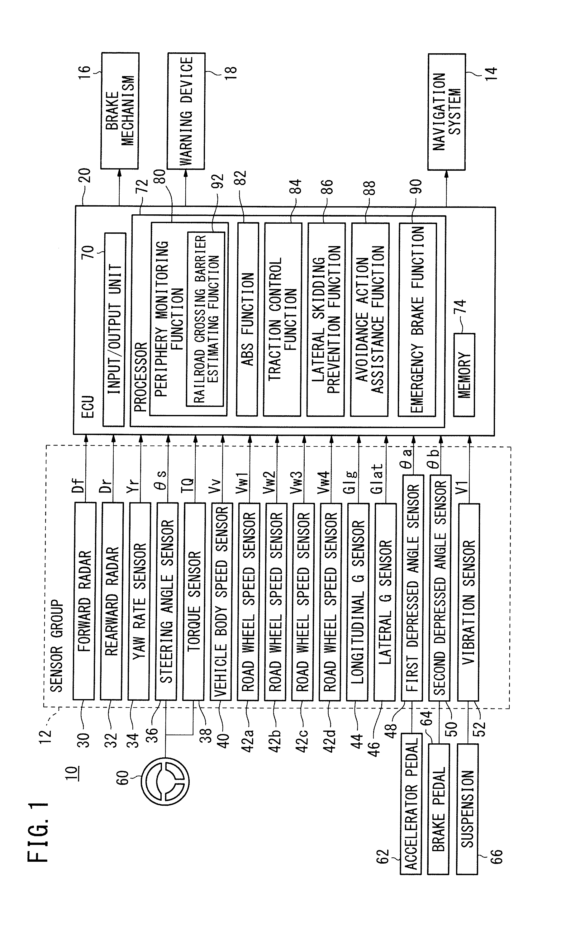
[0027]FIG. 1 shows in block form a vehicle (mobile body) 10 (hereinafter also referred to as a “host vehicle 10”) according to a first embodiment of the present invention.
[0028]As shown in FIG. 1, the vehicle 10 includes a sensor group 12 for detecting various data, a navigation system 14, a brake mechanism 16, a warning device 18, and an electronic control unit (railroad crossing barrier estimating apparatus) 20 (hereinafter referred to as an “ECU 20”).
(1-2. Sensor Group 12)
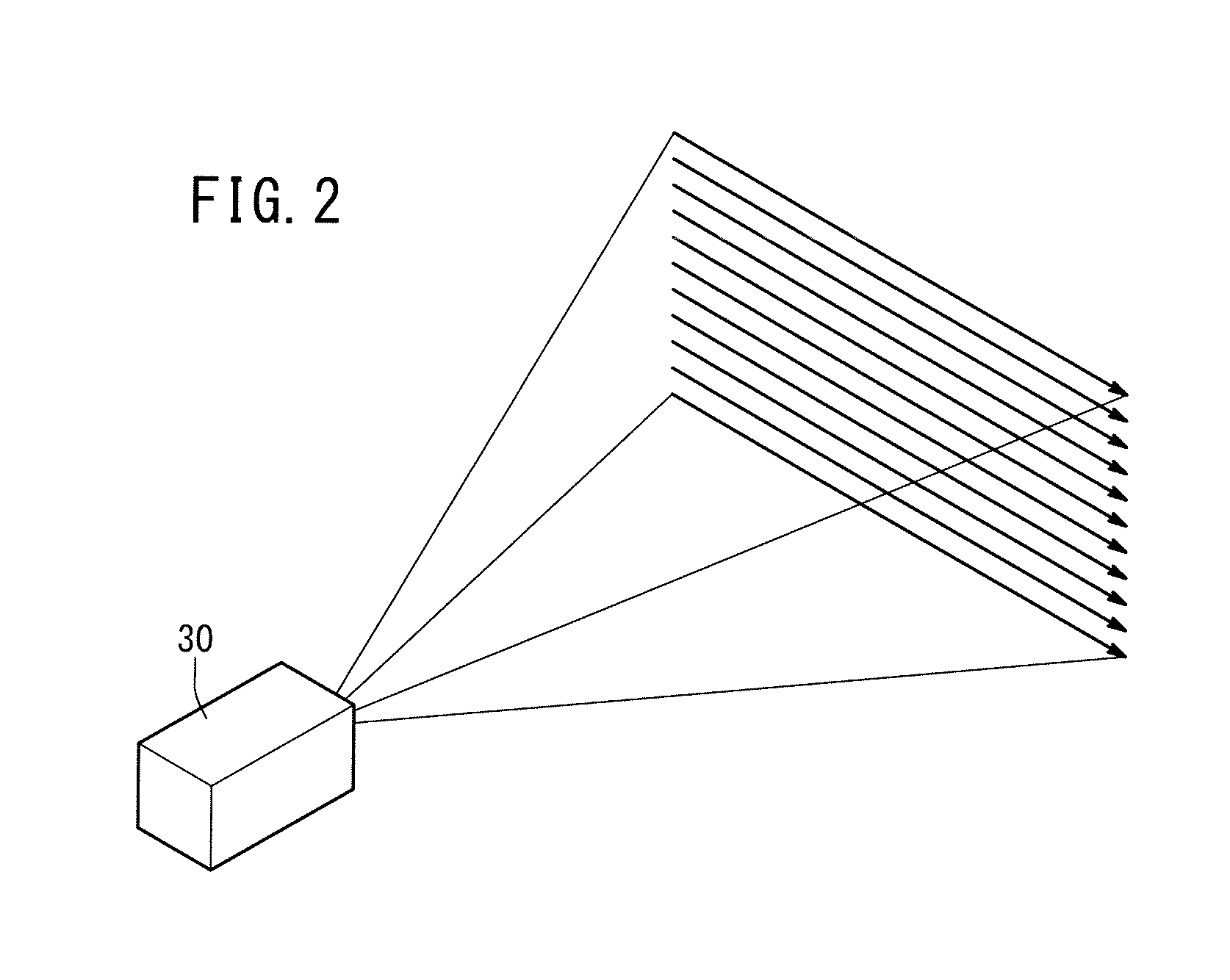
[0029]As shown in FIG. 1, the sensor group 12 includes a forward radar (external object position judger, radar) 30, a rearward radar 32, a yaw rate sensor 34, a steering angle sensor 36, a torque sensor 38, a vehicle body speed sensor (vehicle speed sensor) 40, road wheel speed sensors 42a, 42b, 42c, 42d, a longitudinal G sensor 44, a lateral G sensor 46, a first depressed angle sensor 48, a second depressed angle sensor 50, and a vibration sensor 52...
second embodiment
B. Second Embodiment
1. Configuration
(1-1. Overall Configuration)
[0114]FIG. 11 shows in block form a vehicle (mobile body) 10A (hereinafter also referred to as a “host vehicle 10A”) according to a second embodiment of the present invention.
[0115]The vehicle 10A according to the second embodiment has basically the same configuration as the vehicle 10 according to the first embodiment, but differs therefrom in that a sensor group 12a of the vehicle 10A includes a forward camera (external object position judger, image capturing device) 140 and a rearward camera 142, instead of the forward radar 30 and the rearward radar 32. Also, an electronic control unit (railroad crossing barrier estimating apparatus) 20a (hereinafter referred to as an “ECU 20a”) according to the second embodiment performs the same functions as the ECU 20 according to the first embodiment, except that such functions are performed based on output signals from the forward camera 140 and the rearward camera 142. Compone...
PUM
 Abstract
Description
Claims
Application Information