Actuator

Inactive Publication Date: 2010-09-16
MITSUBISHI ELECTRIC CORP
View PDF5 Cites 8 Cited by
  • Summary
  • Abstract
  • Description
  • Claims
  • Application Information

AI Technical Summary

Benefits of technology

[0006]In accordance with the present invention, the mechanism for preventing rotation of the output axis is constructed of only the connecting portion for connecting the joint, the link plate, and the external device to one another. Therefore, the present invention offers an advantage of being able to prevent occurrence of sticking due to a

Problems solved by technology

A problem with the conventional actuators constructed as mentioned above is that in a case in which a rotation prevention mechanism is disposed in the output axis, the outer diameter of the output axis has to be made thick in order to ensure the mechanical strength of the output axis, and therefore the actuator becomes enlarged.
Another problem is that the provision of the rotation prevention mechanism increases the manufacturing cost of the actuator.
A further problem is that when connected to an external device, because the locking rings are used in the follo

Method used


Image

  • Actuator
  • Actuator
  • Actuator

Examples


embodiment 1

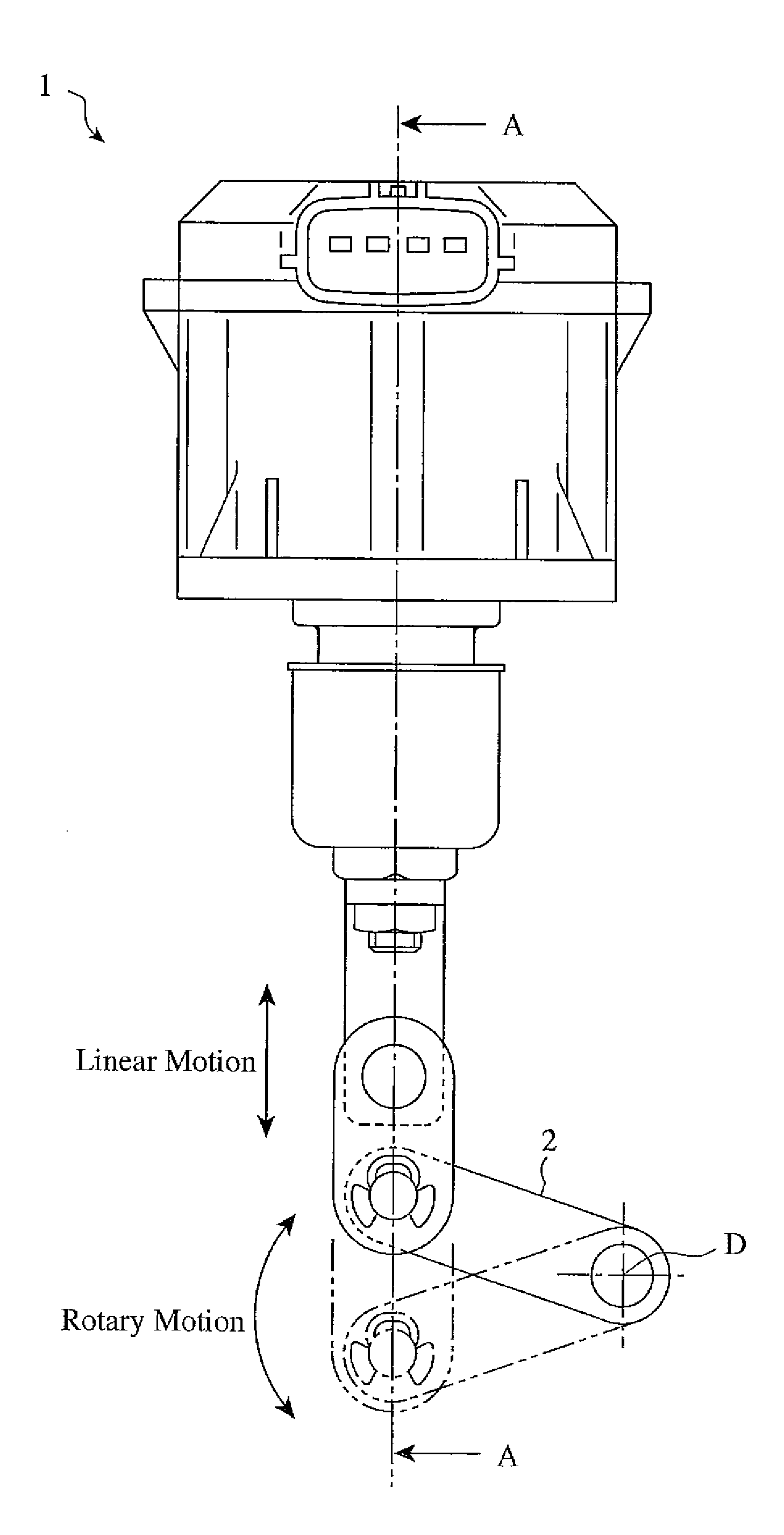
[0016]FIG. 1 is a view showing an example of an actuator 1 in accordance with Embodiment 1 of the present invention. An output axis which is linearly driven by a rotatory force is connected to a lever 2 for adjusting the vane open degree of a turbocharger (not shown), which is disposed as an external device, by way of a connecting member. Reference character D shows a central point around which the lever 2 rotates. This lever 2 rotates around the central point D in a plane parallel to the page of FIG. 1. In this Embodiment 1, an actuator which uses an electromagnetic force (a motor) as a method of rotating the output axis will be explained, though another driving method can be used as long as the use of the other driving method can make the output axis rotate. The actuator in accordance with the present invention can be alternatively connected to another apparatus, as the external device, other than the turbocharger.

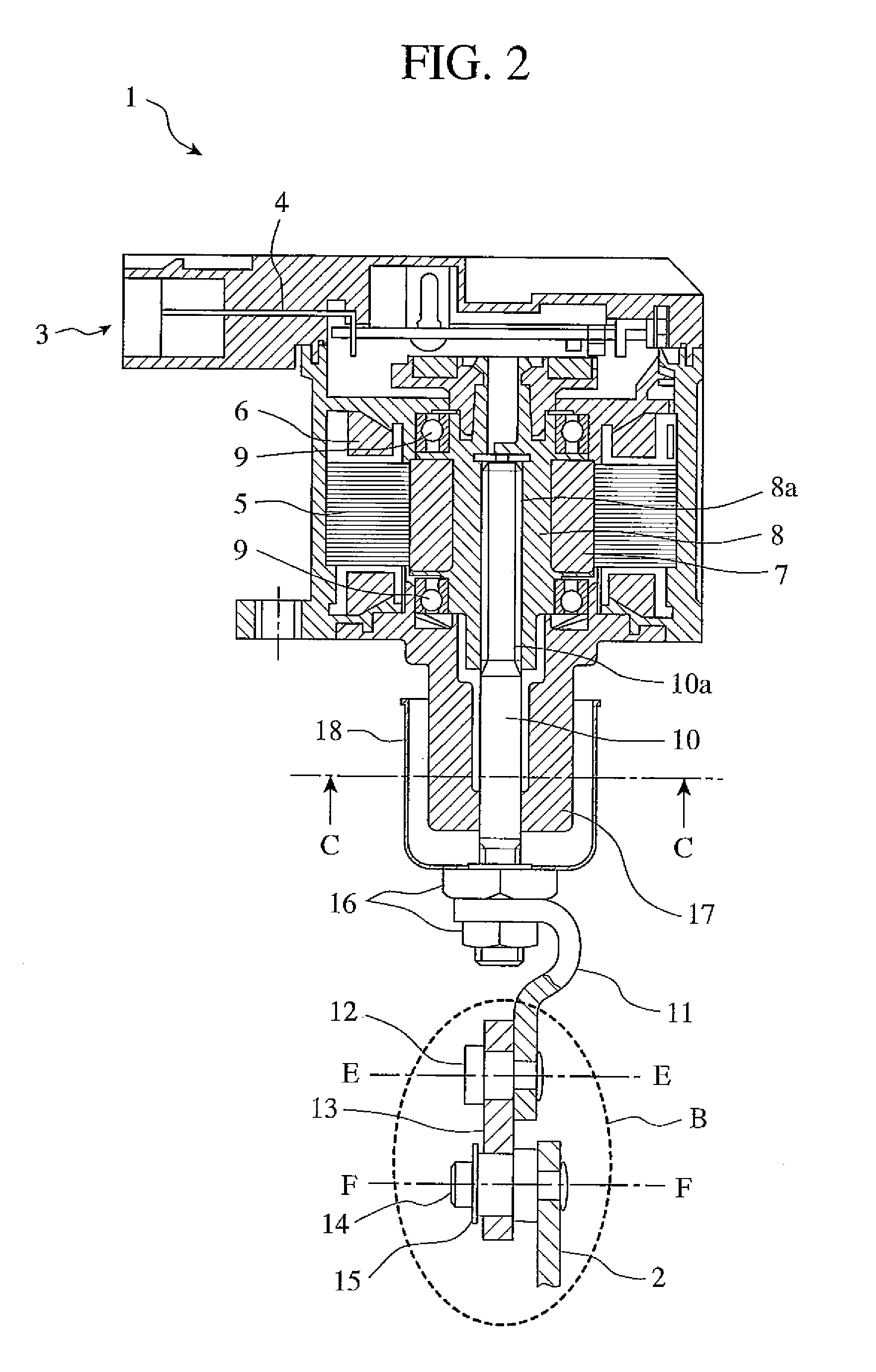
[0017]FIG. 2 is a partially sectional view taken along the A-A line...

embodiment 2

[0024]FIG. 6 is a view showing an actuator 1 in accordance with Embodiment 2, and the actuator in accordance with this embodiment differs from that of Embodiment 1 in that the actuator in accordance with this embodiment includes a boot 19. Hereafter, the same structural components as those explained with reference to FIG. 2 are designated by the same reference numerals as those shown in the figure, and the duplicated explanation of the structural components will be omitted. The boot 19 has an end 19a which is attached to a projecting portion 17a disposed in the boss 17, and another end 19b which is attached to a projecting portion 10b disposed in the output axis 10. Therefore, the boot 19 expands and contracts according to the linear motion of the output axis 10, and prevents an intruder, e.g., a foreign object, such as dust, or a fluid, such as water, from intruding into the actuator from the gap between the output axis 10 and the boss 17. Furthermore, when the actuator 1 is connec...


PUM


Abstract

An actuator having an output axis which is moved linearly by a rotatory force, and a boss for holding the above-mentioned output axis in such a way that the output axis can move linearly includes a connecting member for propagating the linear motion of the above-mentioned output axis to an external device. The above-mentioned connecting member is comprised of a joint connected to the above-mentioned output axis, and a link plate having an end rotatably connected to the above-mentioned joint, and another end rotatably connected to the external device. A mechanism for preventing rotation of the above-mentioned output axis is constructed of only a connecting portion for connecting the above-mentioned joint, the above-mentioned link plate, and the above-mentioned external device to one another.

Description

FIELD OF THE INVENTION[0001]The present invention relates to an actuator equipped with a connecting member for connecting the actuator to an external device.BACKGROUND OF THE INVENTION[0002]As a conventional actuator, there has been provided an actuator, as shown in FIG. 7, in which a plane extending in parallel to the length of an output axis is formed in such a way as to construct a rotation prevention mechanism. In a case in which such an actuator is connected to an external device, a joint 11 connected to the output axis of the actuator is connected to an end of a link plate 13 with a pin 20 and a locking ring 21 in such a way that the joint 1 can rotate around a central axis GG, and another end of the link plate 13 is connected to a lever 2 of the external device with a pin 14 and a locking ring 15 in such a way that the link plate 13 can rotate around a central axis HH, as shown in FIG. 8. Patent reference 1 discloses an actuator in which a notch extending along an axis is for...

Claims


Application Information

Patent Timeline
IPC IPC(8): H02K7/06
CPCH02K7/06
Inventor HATANO, KENTADOI, HIROFUMIMIYAKE, TOSHIHIKO
Owner MITSUBISHI ELECTRIC CORP
Why Eureka
Try Eureka