Brake fill effect minimization function

Active Publication Date: 2010-11-04
THE BF GOODRICH CO
View PDF10 Cites 15 Cited by
  • Summary
  • Abstract
  • Description
  • Claims
  • Application Information

AI Technical Summary

Benefits of technology

[0008]The invention provides a brake fill effect minimization function for preventing or reducing controller windup during a brake fill condition or the like that may commonly occur in hydraulically actuated brakes as well as electromechanically actuated brakes. The function temporarily reduces error input to a controller during perceived brake fill (or running clearance) conditions thereby facilitating smooth application of the brakes during initial braking and/or under anti-skid conditions.
[0009]Accordingly, a system for controlling a braking torque applied to a wheel of a vehicle comprises a power source, at least one brake actuator for exerting a braking force o

Problems solved by technology

Thus, there may be a period of time when the brake command signal does not produce a brake response.
This increased command signal is typically more braking than is desire

Method used


Image

  • Brake fill effect minimization function
  • Brake fill effect minimization function
  • Brake fill effect minimization function

Examples


Embodiment Construction

[0021]The present invention will now be described with reference to the drawings, wherein like reference numerals are used to refer to like elements throughout.

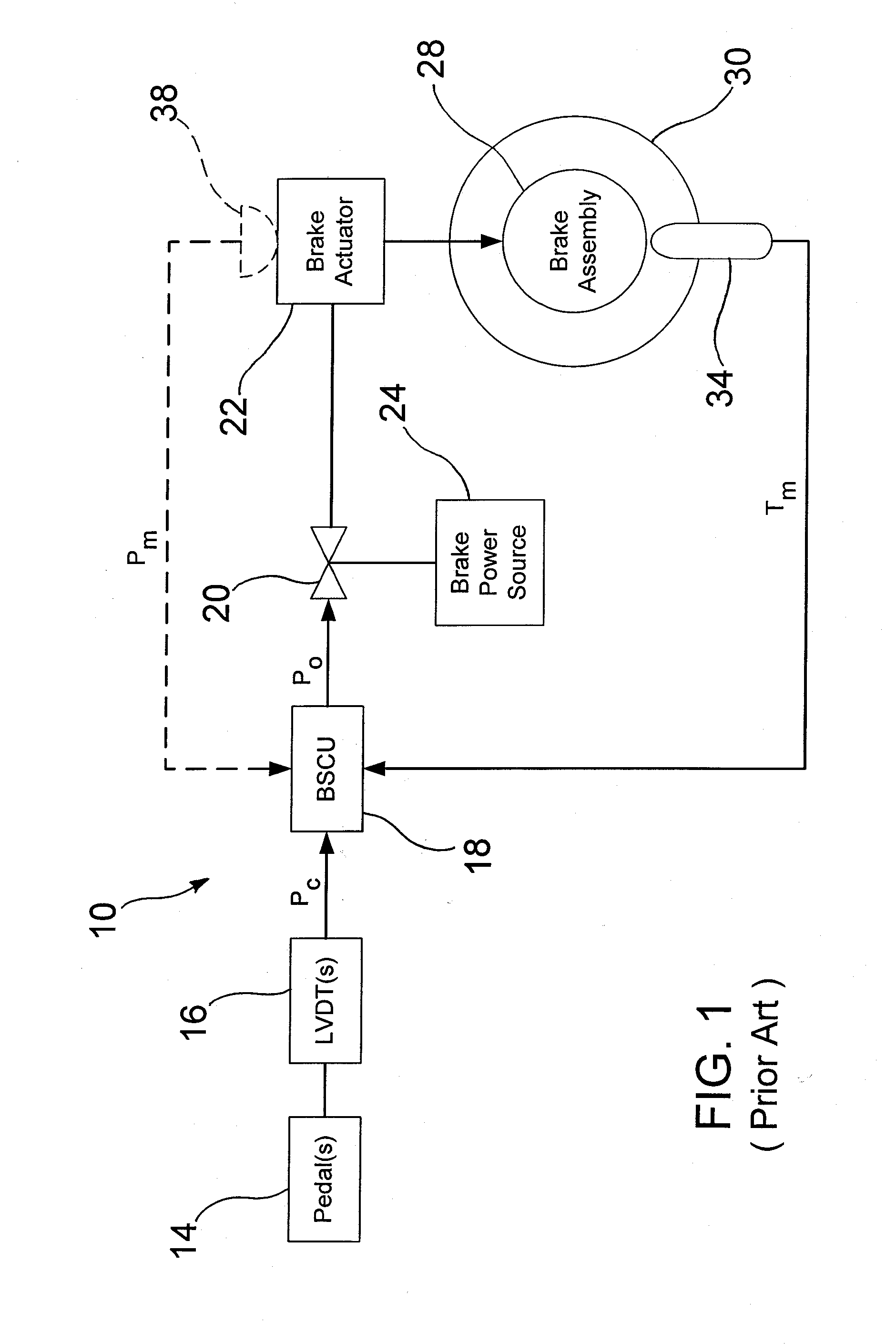
[0022]Referring initially to FIG. 1, a conventional hydraulic brake control system as used in an aircraft is generally designated 10. Generally speaking, brake control on an aircraft is usually structured in a paired wheel configuration for functional modularity. For example, if the aircraft has two wheels on the left side of the aircraft and two wheels on the right side, the outer two wheels form a pair and the inner two wheels form another pair. Within a pair, there is a right wheel control and left wheel control.

[0023]The left and right wheel control functions are uncoupled except possibly for locked wheel protection. The basic unit therefore consists of a control for a single wheel that can be left or right. As utilized herein, it will be appreciated that the term “wheel” is intended to refer collectively to both the whee...


PUM


Abstract

A brake fill effect minimization function for preventing or reducing brake controller windup during a brake fill condition or the like that may commonly occur in hydraulic or electromechanical brake systems, particularly during initial application of the brakes or during anti-skid conditions. The function temporarily reduces error input to the brake controller during a perceived brake fill condition (hydraulic brakes) or running clearance condition (electromechanical brakes) thereby facilitating smooth application of the brakes during initial braking and/or under anti-skid conditions.

Description

FIELD OF THE INVENTION[0001]The present invention relates generally to brake systems for vehicles, and more particularly to brake systems for use in an aircraft.BACKGROUND OF THE INVENTION[0002]Various types of braking systems are known. For example, hydraulic, pneumatic and electromechanical braking systems have been developed for different applications.[0003]An aircraft presents a unique set of operational and safety issues. For example, uncommanded braking due to failure can be dangerous to an aircraft during takeoff. On the other hand, it is similarly necessary to have virtually fail-proof braking available when needed (e.g., during landing). Moreover, it is important that braking be effected promptly and reliably.[0004]A typical hydraulic brake system, for example, may include the following components among others: a pressure source, a brake actuator for exerting a braking force on a wheel as a result of pressure provided by the pressure source, a valve for controlling an amoun...

Claims


Application Information

Patent Timeline
IPC IPC(8): B60T15/14
CPCB60T8/00B60T8/1703B60T8/174B64C25/42B60T2201/12B60T2230/04B60T15/14B60T8/405B60T13/662
Inventor METZGER, JR., RICHARD P.
Owner THE BF GOODRICH CO
Why Eureka
Try Eureka