Image recording device and image reproduction device

a technology of image recording and recording device, which is applied in the field of image recording device and image reproduction device, can solve the problems of more expensive image recording device, and achieve the effect of suppressing image transmission speed

Inactive Publication Date: 2010-11-04
PANASONIC CORP
View PDF13 Cites 12 Cited by
  • Summary
  • Abstract
  • Description
  • Claims
  • Application Information

AI Technical Summary

Benefits of technology

[0024]The image recording device and the image reproduction device according to an implementation of the present invention produces an advantageous effect of suppressing image transmission speed from an imaging device, coding speed, and image recording speed without causing significant image degradation in high-speed image capturing.

Problems solved by technology

Here, for the image recording device to perform high-speed image capturing, it is necessary to increase image transfer speed from the imaging device, coding speed, and image recording speed, and this causes a problem of making the image recording device more expensive.

Method used


Image

  • Image recording device and image reproduction device
  • Image recording device and image reproduction device
  • Image recording device and image reproduction device

Examples


first embodiment

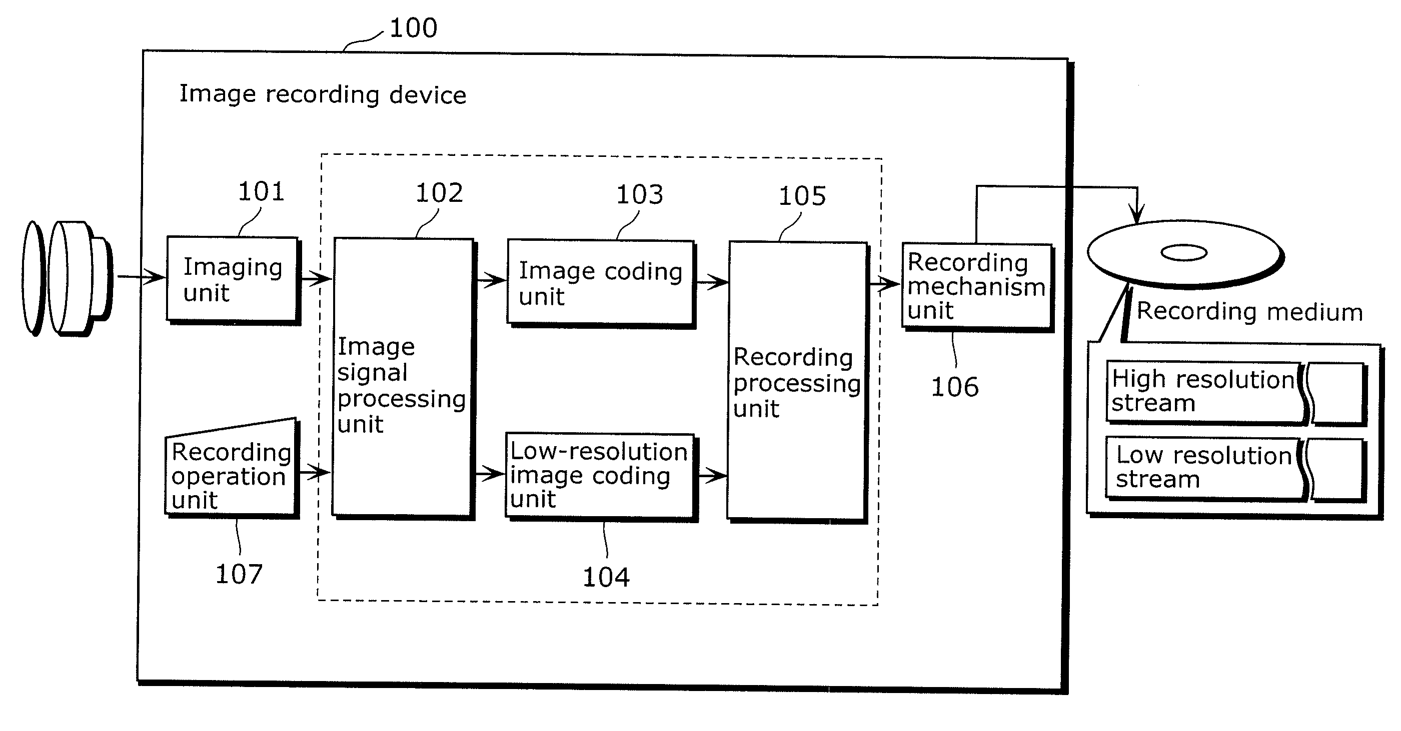
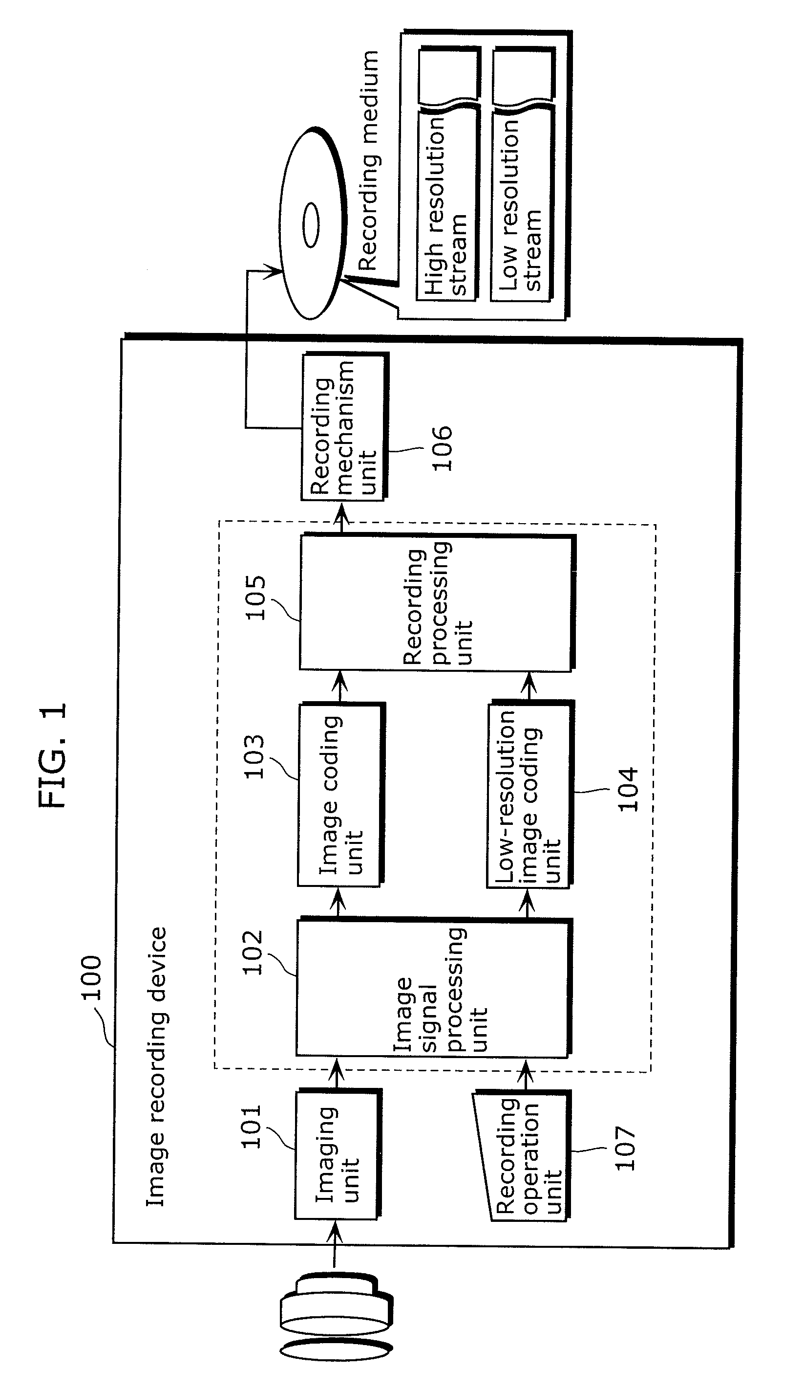
[0052]FIG. 1 is a block diagram showing a configuration of an image recording device according to a first embodiment of the present invention. The image recording device 100 according to the present embodiment includes: an imaging unit 101, an image signal processing unit 102, an image coding unit 103, a low-resolution image coding unit 104, a recording processing unit 105, a recording mechanism unit 106, and a recording operation unit 107.

[0053]The imaging unit 101 includes an imaging device, for example, charge coupled devices (CCD), and generates images each made up of pixels (hereinafter, referred to as captured images) by obtaining an optical signal that is incident through an optical instrument such as a lens and converting the optical signal into an electric signal, that is, by performing image capturing.

[0054]The recording operation unit 107 receives an operation entered by the user. For example, the recording operation unit 107 receives a start or stop command of normal ima...

second embodiment

[0082]FIG. 5 is a block diagram showing a configuration of an image reproduction device according to a second embodiment of the present invention. An image reproduction device 200 in the present embodiment includes: a read processing unit 210, an image decoding unit 211, a low-resolution image decoding unit 212, a resolution conversion unit 213, a reproduction unit 214, a read mechanism unit 215, and a reproduction operation unit 216.

[0083]The reproduction operation unit 216 receives an operation entered by a user. For example, the reproduction operation unit 216 receives a start or stop command of normal reproduction, or receives a start or stop command of slow reproduction.

[0084]The read mechanism unit 215 reads, based on the control performed by the read processing unit 210, a stream (at least one of a high resolution stream and a low resolution stream) stored on the recording medium described above, and outputs the stream to the read processing unit 210.

[0085]The read processing...


PUM


Abstract

An image recording device (100), which can suppress, without causing significant image degradation, image transfer speed from an imaging device, coding speed, and image recording speed that are necessary for high-speed image capturing, includes: an image signal processing unit (102) which sequentially reads, at a frame rate for high-speed image capturing, images generated through image capturing by an imaging unit (101), and outputs, from among the images sequentially read, images read at a frame rate for normal image capturing at high resolution and other images at low resolution; an image coding unit (103) which generates a high resolution coded stream by coding an image sequence made up of the high resolution images outputted by the image signal processing unit (102); a low-resolution image coding unit (104) which generates a low resolution coded stream by coding an image sequence made up of the other low resolution images outputted by the image signal processing unit (102); and a recording processing unit (105) and a recording mechanism unit (106) which record the two streams on a recording medium.

Description

TECHNICAL FIELD[0001]The present invention relates to an image recording device which records an image, and an image reproduction device which reproduces the recorded image.BACKGROUND ART[0002]An image recording device, such as a camcorder which includes an imaging device such as charge coupled devices (CCD), transfers an image generated by the imaging device, codes the image, and records the coded image. Here, for the image recording device to perform high-speed image capturing, it is necessary to increase image transfer speed from the imaging device, coding speed, and image recording speed, and this causes a problem of making the image recording device more expensive.[0003]Thus, an image recording device which has been conventionally proposed performs high-speed image capturing without increasing the image transfer speed from the imaging device, the coding speed, and the image recording speed (For example, see Patent Reference 1).[0004]FIG. 10 is an illustrative diagram for descri...

Claims


Application Information

Patent Timeline
Patent Type & Authority Applications(United States)
IPC IPC(8): H04N5/76
CPCG11B20/1262G11B2020/00079G11B2020/10537H04N5/85G11B2220/2537H04N5/232H04N5/77G11B2020/1289H04N23/63
Inventor SEKI, YUKINAGAKOBAYASHI, YUKICHIBA, TAKUMATSUDA, KENJIROSHIMAZAKI, HIROAKIJURI, TATSUROSAIGO, KATSUOMASUNO, TAKASHI
Owner PANASONIC CORP
Why Eureka
Try Eureka