Vehicular lighting fixture

Inactive Publication Date: 2010-12-09
STANLEY ELECTRIC CO LTD
View PDF11 Cites 10 Cited by
  • Summary
  • Abstract
  • Description
  • Claims
  • Application Information

AI Technical Summary

Benefits of technology

[0027]According to the third aspect of the presently disclosed subject matter, since the inclination angle of the fourth reflection surface with respect to the horizontal plane is set in the range of 5 to 30 degrees, it is possible to prevent reflected light from the fourth reflection surface from being incident on the projection lens so as to cause a dark zone to be newly formed, and can also prevent the reflected light from th

Problems solved by technology

However, in the case where only the fourth reflection surface is provided, the light intensity in the region immediately below the second additional

Method used


Image

  • Vehicular lighting fixture
  • Vehicular lighting fixture
  • Vehicular lighting fixture

Examples


Embodiment Construction

[0039]In the following, an example of a vehicular lighting fixture made in accordance with principles of the presently disclosed subject matter, will be described with reference to the accompanying drawings.

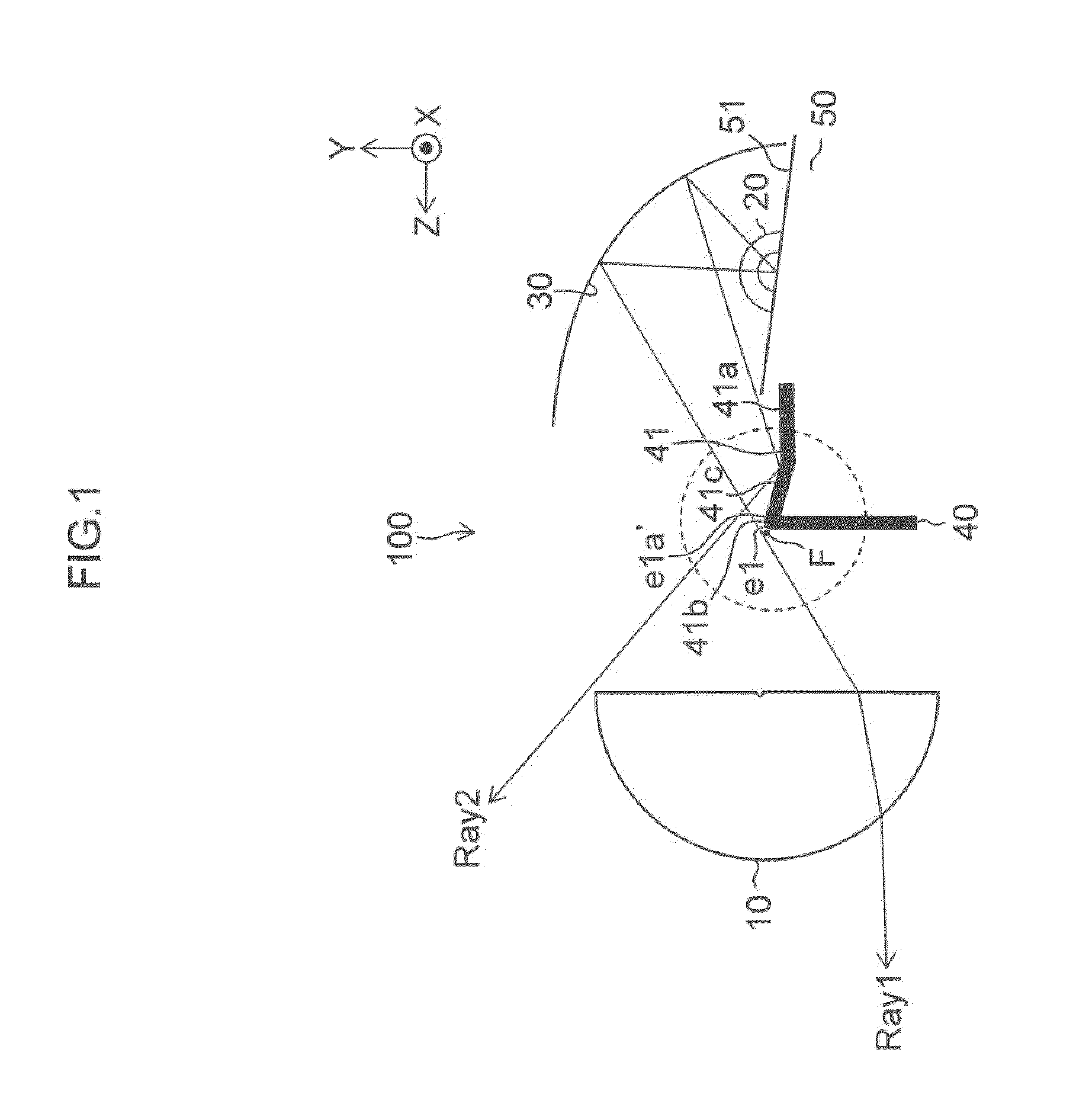
[0040]A vehicular lighting fixture 100 according to the present exemplary embodiment can be applied to a head lamp of a vehicle, such as a motor vehicle, and can include a projection lens 10 arranged on the front side of the vehicle. An LED light source 20 can be arranged on the rear side of the vehicle, and a first reflection surface 30 can be arranged in the irradiation direction of the LED light source 20. A shade 40 can be arranged between the projection lens 10 and the LED light source 20, as illustrated in FIG. 1.

[0041]The projection lens 10 can be configured as a non-spherical condenser lens whose focus F is arranged on the side of the LED light source 20. The projection lens 10 can also be configured to project light along a light emitting axis (for example, along an axis...


PUM


Abstract

A vehicular lighting fixture can include a shade wherein an end edge of an upper surface of the shade is positioned at or in a vicinity of a focus of a projection lens. A first reflection surface can be provided to condense light from a light source in a vicinity of the end edge and to form a basic light distribution pattern by the projection lens. A second reflection surface which can comprise one planar reflection surface and can reflect light from the first reflection surface to form a first additional light distribution pattern. A third reflection surface can be provided on a higher surface of a step section of the upper surface, and can reflect light from the first reflection surface to form a second additional light distribution pattern. A fourth reflection surface can connect the second and third reflection surface, and can reflect the light from the first reflection surface in a direction not incident on the projection lens.

Description

CROSS-REFERENCE TO RELATED APPLICATIONS[0001]This application claims the priority benefit under 35 U.S.C. §119 of Japanese Patent Application No. 2009-135505 filed on Jun. 4, 2009, which is hereby incorporated in its entirety by reference.BACKGROUND[0002]1. Field[0003]The presently disclosed subject matter relates to a vehicular lighting fixture, and more particularly to a vehicular lighting fixture capable of preventing a dark zone from being formed in a synthesized light distribution pattern.[0004]2. Description of the Related Art[0005]Conventionally, a vehicular lighting fixture which forms a synthesized light distribution pattern by a plurality of light distribution patterns is known (see, for example, Japanese Patent No. 4080780).[0006]FIG. 6 illustrates an example of a vehicular lighting fixture which forms a synthesized light distribution pattern by a plurality of light distribution patterns. FIG. 7 is a perspective view of a shade used in the vehicular lighting fixture illus...

Claims


Application Information

Patent Timeline
IPC IPC(8): B60Q1/04
CPCF21S48/1159F21S48/1388F21S48/1317F21S41/255F21S41/321F21S41/43F21S45/47F21S41/365F21S41/148
Inventor YAMAGATA, SHINJI
Owner STANLEY ELECTRIC CO LTD
Why Eureka
Try Eureka