Current sensor

a current sensor and sensor technology, applied in the field of current sensors, can solve the problems of deteriorating work efficiency, affecting the accuracy of measurement, and hardly meeting the electrical wires of different outside diameters of current sensors, so as to prevent the backlash of the case and the cover, the effect of accurate measurement and preventing the backlash of the cover

Inactive Publication Date: 2010-12-16
YAZAKI CORP
View PDF31 Cites 29 Cited by
  • Summary
  • Abstract
  • Description
  • Claims
  • Application Information

AI Technical Summary

Benefits of technology

[0023]According to the above configurations, since the cover is formed in an annular shape having a gap along an extending direction of the conductor, a magnetic flux generated from the conductor when the current is supplied to the conductor is combined with a magnetic flux generated in the gap by the magnetic flux to generate an area where the change of a magnetic flux density is flat between the conductor and the gap. Electrical parts are arranged in this area,

Problems solved by technology

However, in the current sensors described in the patent literatures 1 to 3, a problem arises that the current sensors hardly meet the electric wires having different outside diameters.
However, during these works, a problem arises that the current sensor collides with a periphery to be failed or the current sensor interferes with the work to deteriorate the efficiency of the work.
Further, when the current sensor is brought into a failure after the electric wi

Method used


Image

  • Current sensor
  • Current sensor
  • Current sensor

Examples


Embodiment Construction

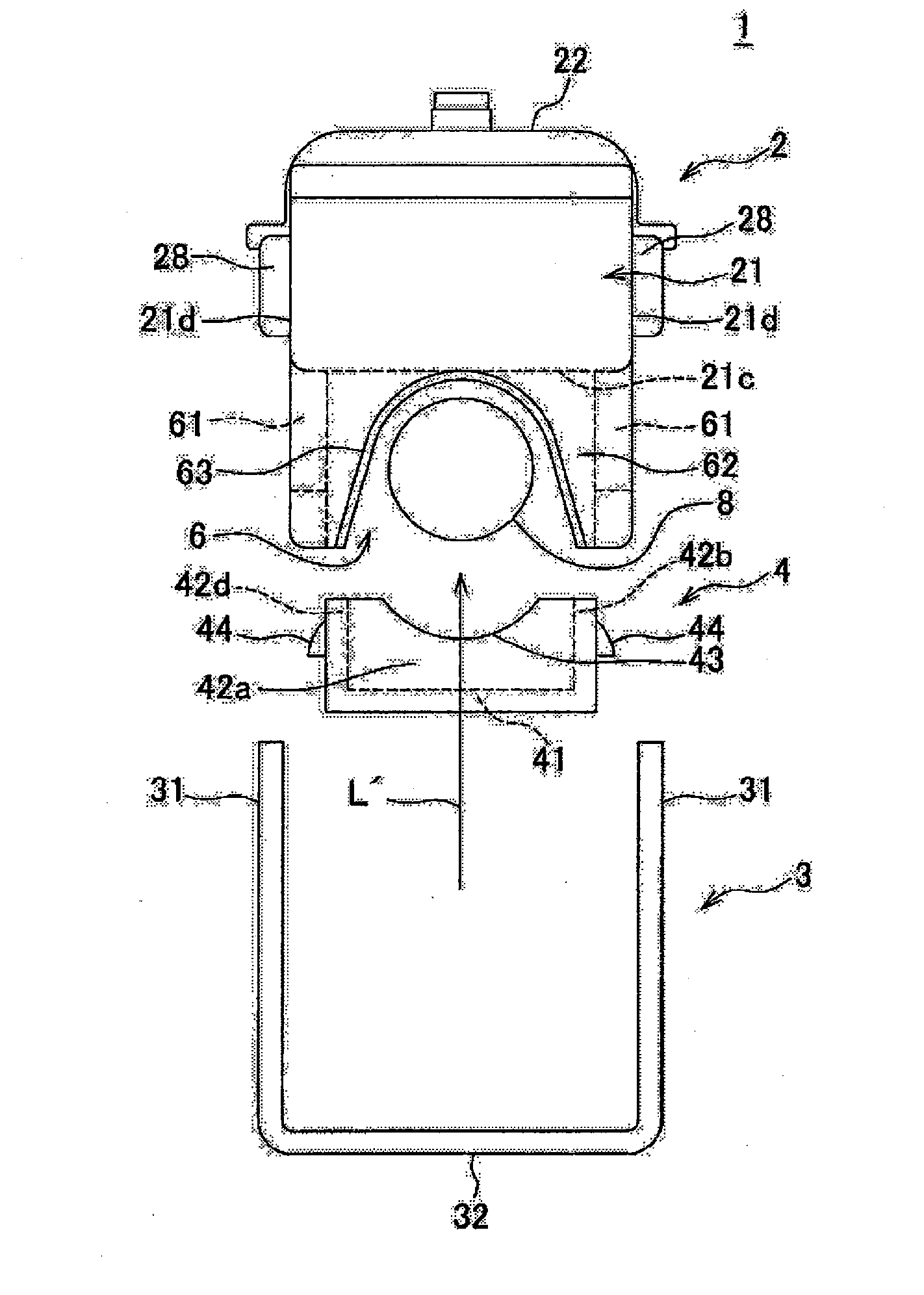
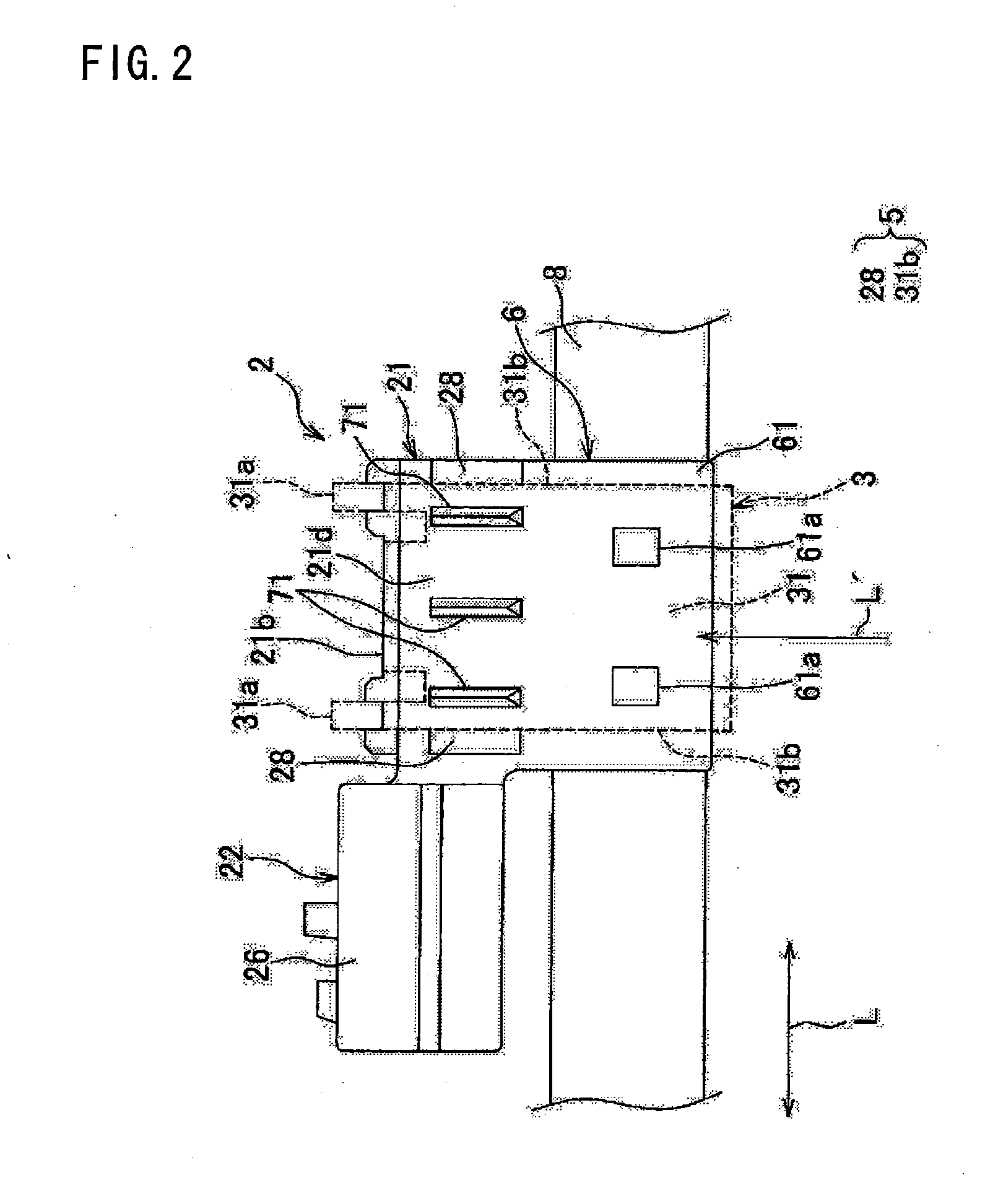
[0039]A current sensor according to a first embodiment of the present invention will be described below by referring to FIGS. 1 to 7. The current sensor 1 is attached to an electric wire (a conductor) 8 as shown in FIG. 2 to measure a current supplied to the electric wire 8. The current sensor 1 includes, as shown in FIG. 1, a case 2, a cover 3, a fixing member 4 and a positioning portion 5 (FIG. 2).

[0040]For example, the electric wire 8 forms a wire harness arranged in a motor vehicle as a mobile body. The electric wire 8 includes an electrically conductive core wire and an insulating coating part. The core wire is formed by twisting a plurality of element wires. The element wire forming the core wire is made of an electrically conductive metal material. Further, the core wire may be formed with one element wire. The coating part is made of, for instance, a synthetic resin such as polyvinyl chloride. The core wire is coated with the coating part. The core wire and the coating part ...


PUM


Abstract

A current sensor for measuring a current supplied to a conductor includes a case which accommodates an electrical parts therein, and a cover attached to the case. A groove part is provided on an outer surface of at least one of the case and the cover to allow the conductor to pass through the groove part. When the cover is attached to the case, the conductor arranged on the groove part is sandwiched between the case and the cover. A width of the groove part becomes narrower toward an interior side thereof.

Description

TECHNICAL FIELD[0001]The present invention relates to a current sensor attached to a conductor to measure a current supplied to the conductor.BACKGROUND ART[0002]As a current sensor attached to an electric wire to measure a current supplied to the electric wire, for instance, below-described current sensors have been hitherto known (for instance, see patent literatures 1 to 3).[0003]The current sensor described in the patent literature 1 includes a case in which electrical parts are accommodated and a cover. The case is formed in a cylindrical shape with a bottom including a bottom wall of a doughnut form in a plan and peripheral walls standing from an inner edge and an outer edge of the bottom wall. The cover is attached to the case so as to cover an opening of the case therewith. In the cover, a tubular guide part is provided that is allowed to pass through the center part of the case and allows an electric wire to pass through an inner part thereof. The inside diameter of the tub...

Claims


Application Information

Patent Timeline
IPC IPC(8): G01R1/04
CPCG01R1/06788G01R15/20G01R31/006
Inventor HASHIO, SHINICHIMOCHIZUKI, TOSHIROAI, TAKESHISUGIMORI, YASUHIROKAWAGUCHI, YASUNORI
Owner YAZAKI CORP
Why Eureka
Try Eureka