Method for calibrating antenna arrays

a technology of antenna arrays and antenna arrays, applied in the field of self-testing antenna arrays, can solve the problems of large dynamic range required from the rx channel, a lot of additional components for calibration, and additional control mechanisms

Inactive Publication Date: 2010-12-23
ALVARION
View PDF10 Cites 26 Cited by
  • Summary
  • Abstract
  • Description
  • Claims
  • Application Information

AI Technical Summary

Benefits of technology

[0008]It is an object of the present invention to provide a method that will allow implementing self testing and calibration of antenna array while still using existing st...

Problems solved by technology

The disadvantage of applying the scheme disclosed by this publication is that it requires additional radio unit with TX/RX calibration channels and additional control mechanisms to control and synchronize the calibration transmissions together with the regular modem transmissions.
However, the limitation of this approach is the large dynamic range requir...

Method used


Image

  • Method for calibrating antenna arrays
  • Method for calibrating antenna arrays
  • Method for calibrating antenna arrays

Examples


Embodiment Construction

[0055]A better understanding of the present invention is obtained when the following non-limiting detailed description is considered in conjunction with following figures.

[0056]As was previously explained, it is necessary to calibrate the amplitude and phase errors between the radio channels due to differences in the RF devices resulting from tolerances and operating frequencies in the antenna array. Since these errors tend to change over time e.g. due to temperature variations, real-time dynamic calibration is essential.

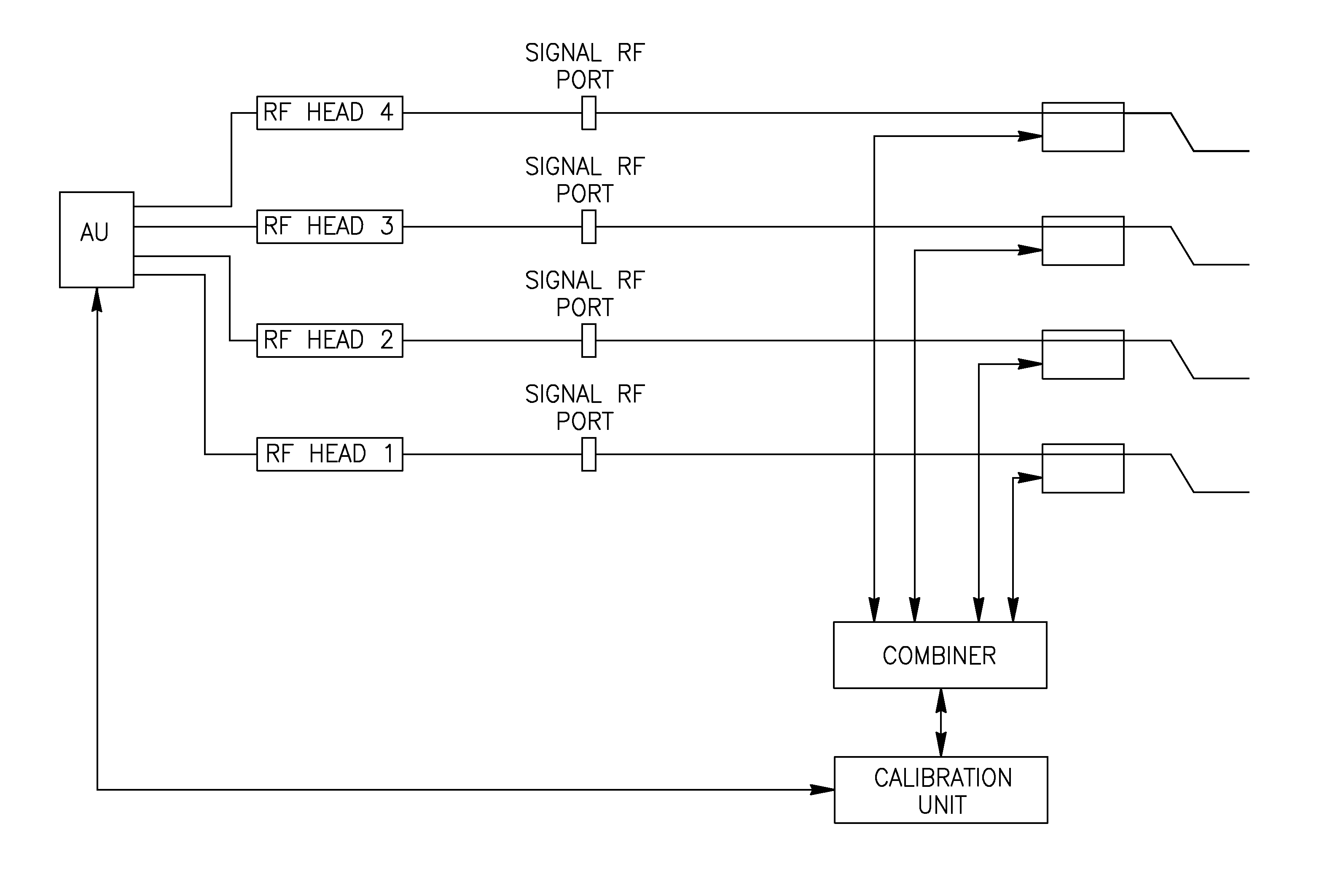
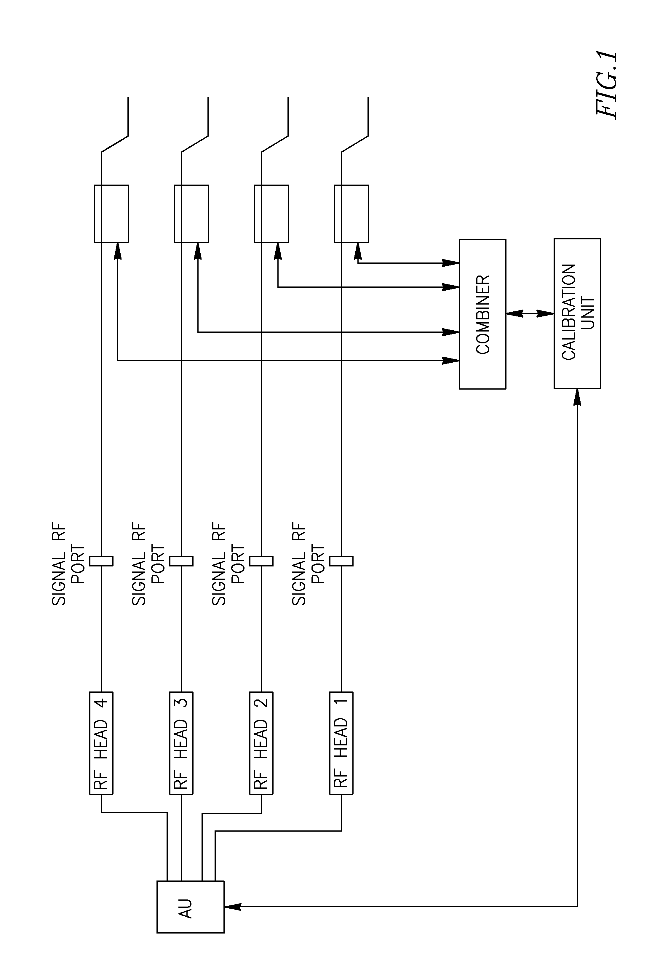
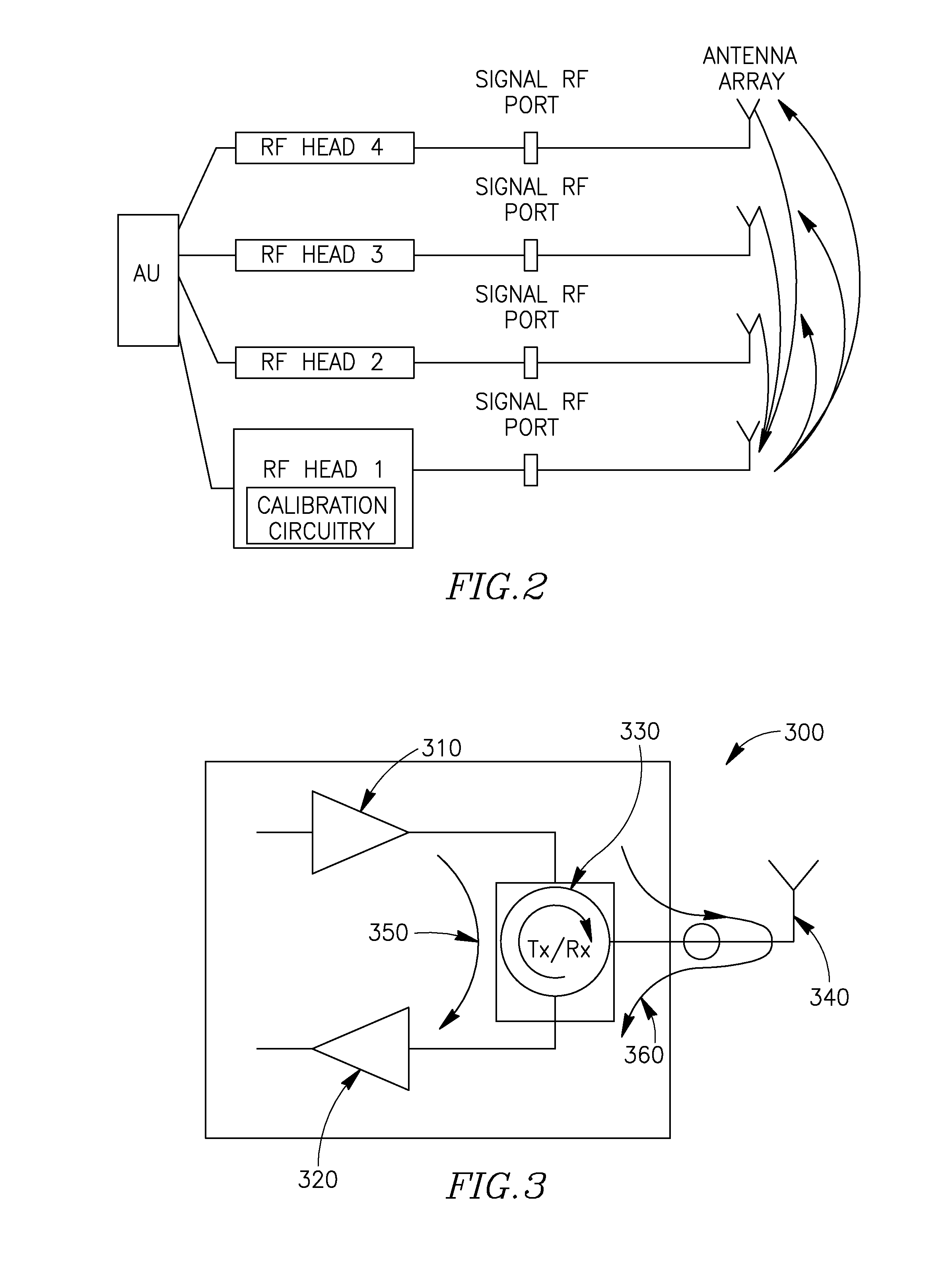
[0057]The commonly used methods today to cope with this need are the use of an external calibration unit as shown in FIG. 1 and the use of a self-calibration mechanism as demonstrated in FIG. 2.

[0058]As may be seen in FIG. 1, the major disadvantage of the external calibration scheme is that it requires additional radio unit with TX / RX calibration channels and additional control mechanisms to control and synchronize the calibration transmissions together with the reg...


PUM


Abstract

A method is provided for use in calibrating a plurality of antennas comprised in an antenna array and wherein the antenna array comprises at least one gain control circuitry. The method comprises: transmitting one or more pre-defined signals by at least one antenna comprised in the antenna array; receiving at one or more of the antennas comprised in the antenna array, a signal derived from a corresponding pre-defined signal transmitted by the at least one antenna; and for each of the one or more antennas, detecting whether there is any difference between the corresponding one or more pre-defined signals transmitted thereto and the respective one or more signals received thereat, and if in the affirmative, applying the detected differences in a process of calibrating the one or more antennas comprised in the antenna array, and wherein the process of calibrating the one or more antennas comprised in the antenna array comprises a step of estimating a ratio of complex transmission coefficients for at least two states of the at least one gain control circuitry.

Description

FIELD OF THE INVENTION [0001]The present invention relates to a method for self testing antenna arrays in wireless systems. In particularly the present invention relates to the calibration of antenna arrays in such systems.BACKGROUND OF THE INVENTION [0002]Exchange of communications between a subscriber device and a base station which comprises an adaptive antenna array, is carried out by transmitting communications from the base station towards the subscriber device using a beam generated by the base station and directed towards the subscriber device (referred to herein as “beam-forming” or “BF”). In order to ensure successful transmission and reception of communications to / from the subscriber, the base station must ensure that the antenna array used is properly calibrated. Typically, this type of operation, i.e. checking the antenna array calibration, is carried out every second up to about a minute time interval.[0003]The BF is especially effective in TDD systems because the same...

Claims


Application Information

Patent Timeline
IPC IPC(8): G01S7/40
CPCH01Q3/267
Inventor BEN-ZUR, AVRA'AMDELISHANSKY, MICHAELSHECHTER, DAVID
Owner ALVARION
Why Eureka
Try Eureka