Method of assembling metal clamp and body springs of wiper blade for vehicle and assembly

a technology of metal clamps and wiper blades, which is applied in the direction of vehicle maintenance, vehicle cleaning, manufacturing tools, etc., can solve the problems of deteriorating assembly productivity, complicated wiper blade structure, and increased manufacturing costs of wiper blades, so as to improve the rigidity of wiper blades, reduce clamp deformation, and ensure the effect of us

Active Publication Date: 2011-02-24
CAP CORP
View PDF4 Cites 47 Cited by
  • Summary
  • Abstract
  • Description
  • Claims
  • Application Information

AI Technical Summary

Benefits of technology

[0015]According to the technical solution of an embodiment of the present invention as described above, it is possible to achieve secure coupling between the clamp and the body springs and to reduce deformation in shape of the clamp, thereby achieving stable use of a wiper blade in snow as well as in rain and, in addition, improving rigidity of the wiper blade.

Problems solved by technology

As a result, the number of parts to be assembled is large, and therefore, the structure of the wiper blade is very complicated while manufacturing costs of the wiper blade are greatly increased.
In addition, a process of assembling the wiper blade is also complicated in proportion to the number of parts to be assembled, with the result that assembly productivity is also deteriorated.
As a result, the conventional wiper blade does not satisfy a snow block test during development of products, and, in addition, the shape of the clamp may be deformed.
As a result, the coupling between the clamp and the body springs may loosen during use of the wiper blade for a long period of time, and therefore, the wiper blade may malfunction and thus stable use of the wiper blade may not be achieved.
As a result, the overall size of the clamp 130 is large, and therefore, material costs are increased.

Method used


Image

  • Method of assembling metal clamp and body springs of wiper blade for vehicle and assembly
  • Method of assembling metal clamp and body springs of wiper blade for vehicle and assembly
  • Method of assembling metal clamp and body springs of wiper blade for vehicle and assembly

Examples


Embodiment Construction

[0052]Various embodiments have been described in the best mode for carrying out the invention.

INDUSTRIAL APPLICABILITY

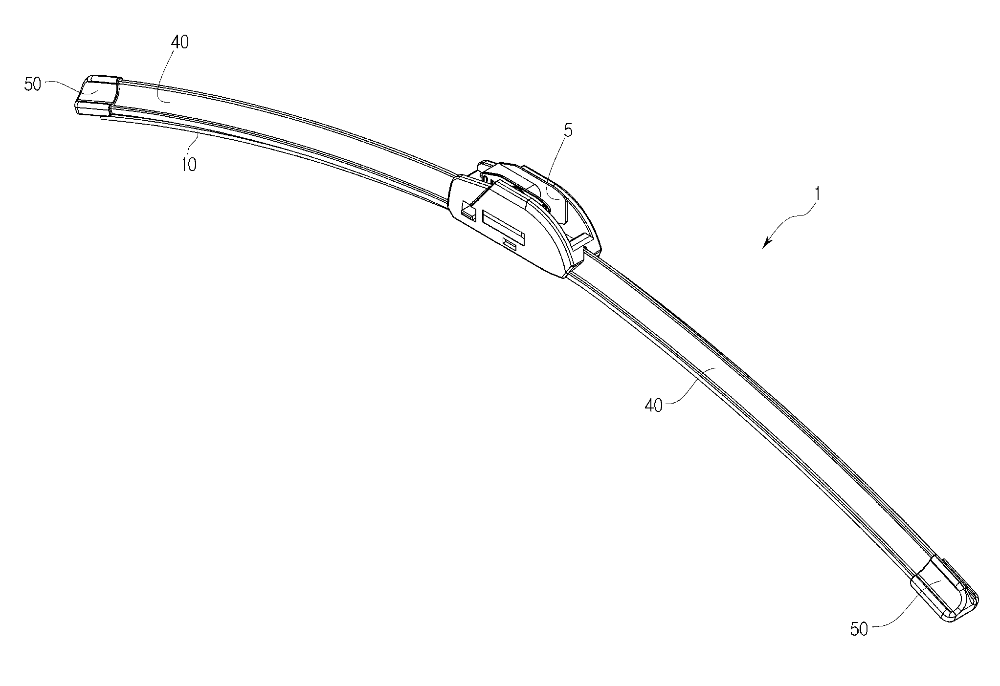
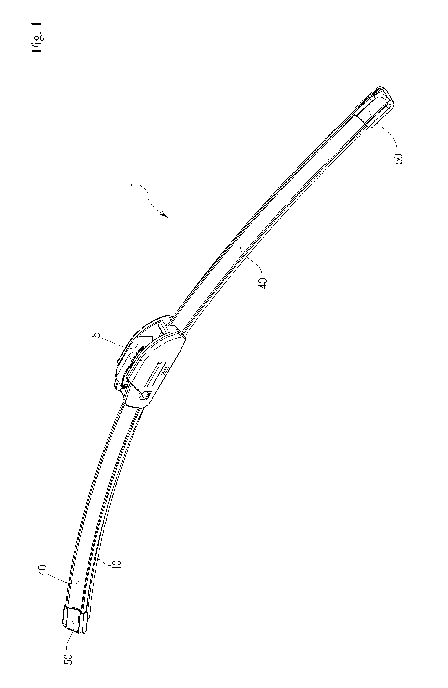
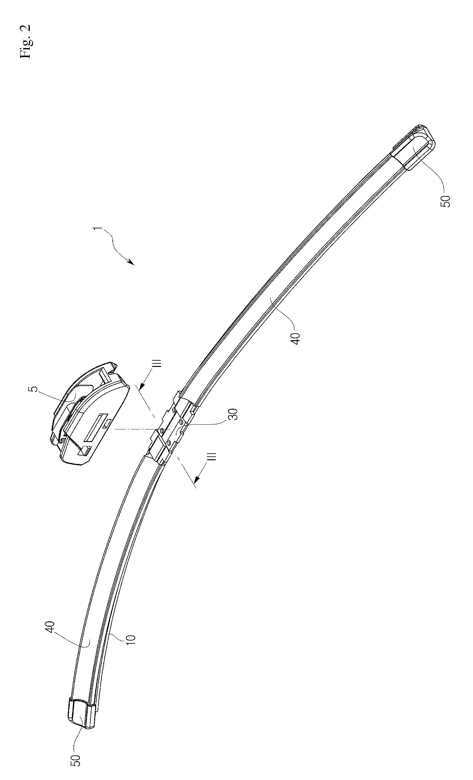
[0053]According to an embodiment of the present invention, as is apparent from the above description, a plurality of protrusions may be formed at a major side of a clamp, which may be made of a metal material, in a protruding manner such that the protrusions may correspond to through holes formed in body springs, the protrusions of the clamp may be fixed in the corresponding through holes of the body springs by pressure welding or riveting such that the clamp may be mounted to the body springs, thereby achieving secure coupling between the clamp and the body springs, reducing deformation in shape of the clamp, and achieving stable use of a wiper blade in snow as well as in rain. Consequently, an embodiment of the present invention with the above-stated construction has industrial applicability.

[0054]It will be apparent to those skilled in the art that various modific...


PUM

PropertyMeasurementUnit
radius of curvatureaaaaaaaaaa
toughnessaaaaaaaaaa
ductilityaaaaaaaaaa

Abstract

Disclosed is a method of assembling a metal clamp and body springs of a wiper blade for vehicles, and an assembly. The method includes forming a plurality of through holes at major sides of the body springs, forming a plurality of protrusions corresponding to the through holes at a major side of the clamp such that the protrusions extend outward from the major side of the clamp, inserting the protrusions of the clamp into the respective through holes of the body springs, fixing the protrusions, which are located in the respective through holes, in the respective through holes by pressure welding or riveting such that the clamp is mounted to the body springs.

Description

RELATED APPLICATIONS[0001]This application claims priority under 35 U.S.C. 119(e) from Korean Patent Application No. 10-2009-0077656, filed Aug. 21, 2009 in the Korean Intellectual Property Office, which is incorporated herein by reference in its entirety.TECHNICAL FIELD[0002]Embodiments of the present invention relate to a method of assembling a metal clamp and body springs of a wiper blade for vehicles, and an assembly.BACKGROUND ART[0003]Generally, a wiper mounted to a windshield glass of a vehicle serves to prevent forward visibility of a driver from being disturbed due to rain or snow present on the windshield glass during driving of the vehicle in rain or in snow and, in addition, to wipe the windshield glass clean. Specifically, a wiper system is mounted at a predetermined part of a body of the vehicle below the windshield glass of the vehicle, and a wiper blade performs reciprocation, i.e., alternating motions, on the windshield glass from side to side in a fan shape when th...

Claims


Application Information

Patent Timeline
Patent Type & Authority Applications(United States)
IPC IPC(8): B60S1/32B23P17/04
CPCB60S1/3855Y10T29/49826B60S1/3879B60S1/3858B60S1/32B60S1/40
Inventor CHOI, YONG KIKIM, TAE HUNLEE, DONG GEUNLEE, SANG CHEOL
Owner CAP CORP
Why Eureka
Try Eureka