Power factor improvement circuit

a technology of power factor and protection circuit, which is applied in the direction of climate sustainability, dc-dc conversion, power conversion systems, etc., can solve the problems of large increase in consumption power of protection circuit, short time-consuming increase in output voltage of power factor improvement circuit, etc., to reduce power at the time of electronic device standby, increase the degree of design freedom, and reduce the effect of over-voltage detection resistan

Inactive Publication Date: 2011-03-03
SANKEN ELECTRIC CO LTD
View PDF7 Cites 9 Cited by
  • Summary
  • Abstract
  • Description
  • Claims
  • Application Information

AI Technical Summary

Benefits of technology

According to the invention, the loss at the time of the standby of an electronic device, which is caused due to the over-voltage detection resistance of the power factor improvement circuit, is removed and the power at the time of the standby of the electronic device can be thus reduced. In addition, since it is not necessary to consider the power at the time of standby, it is possible to make the over-voltage detection resistance be relatively small. According thereto, it is possible to increase a degree of freedom of the design and to improve the foreign noise tolerated dose of the over-voltage protection circuit.

Problems solved by technology

However, since the response is slow, a problem is caused in which the output voltage is increased in a short time due to sudden changes in inputs and loads.
However, in the above-described related-art power factor improvement circuit, since the latch-type output over-voltage detection circuit 81 is connected, the consumption power of the power factor improvement circuit is consumed.
Thus, the increase in consumption power by the protection circuit is a big problem.

Method used


Image

  • Power factor improvement circuit
  • Power factor improvement circuit
  • Power factor improvement circuit

Examples


Embodiment Construction

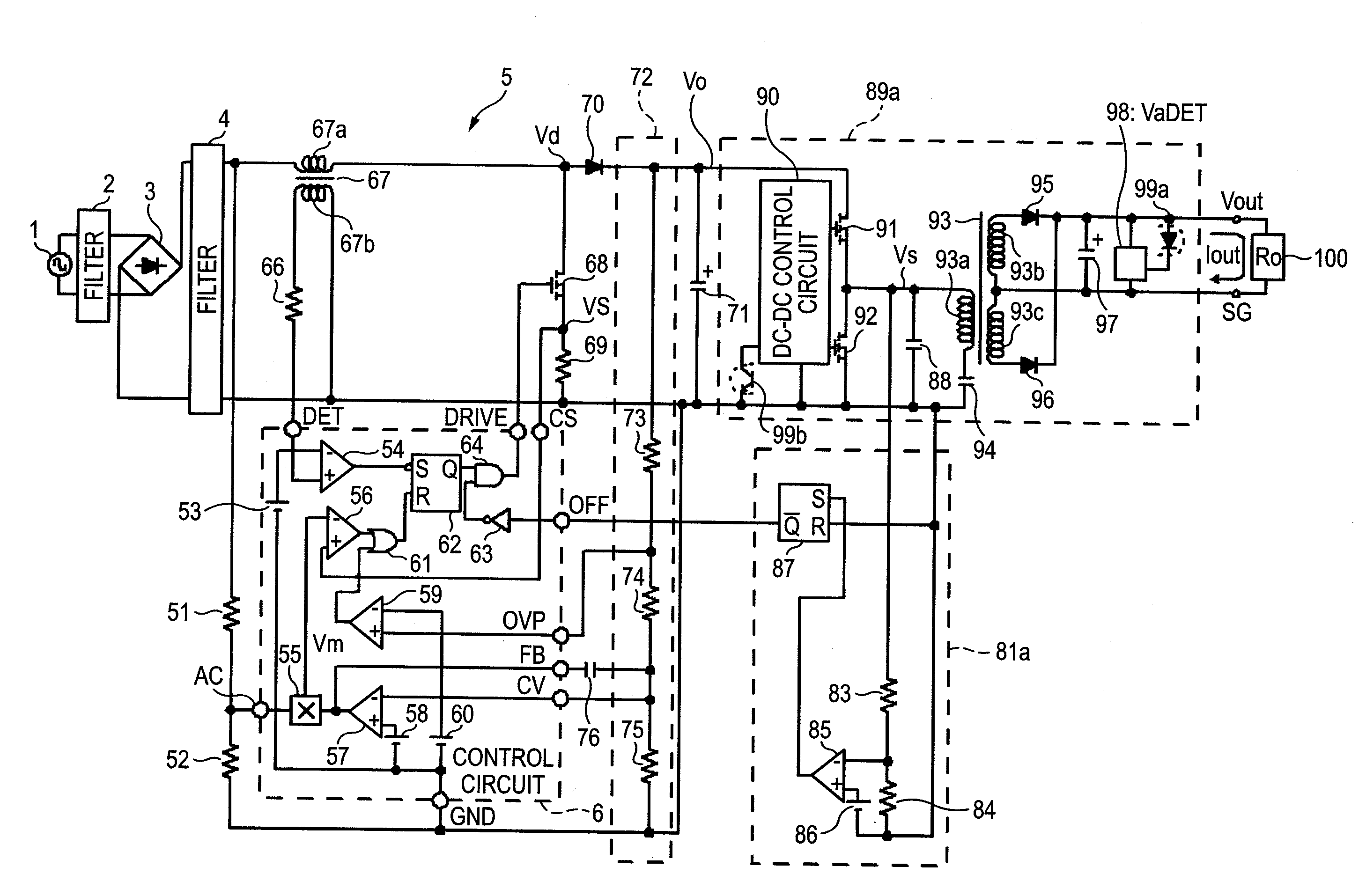
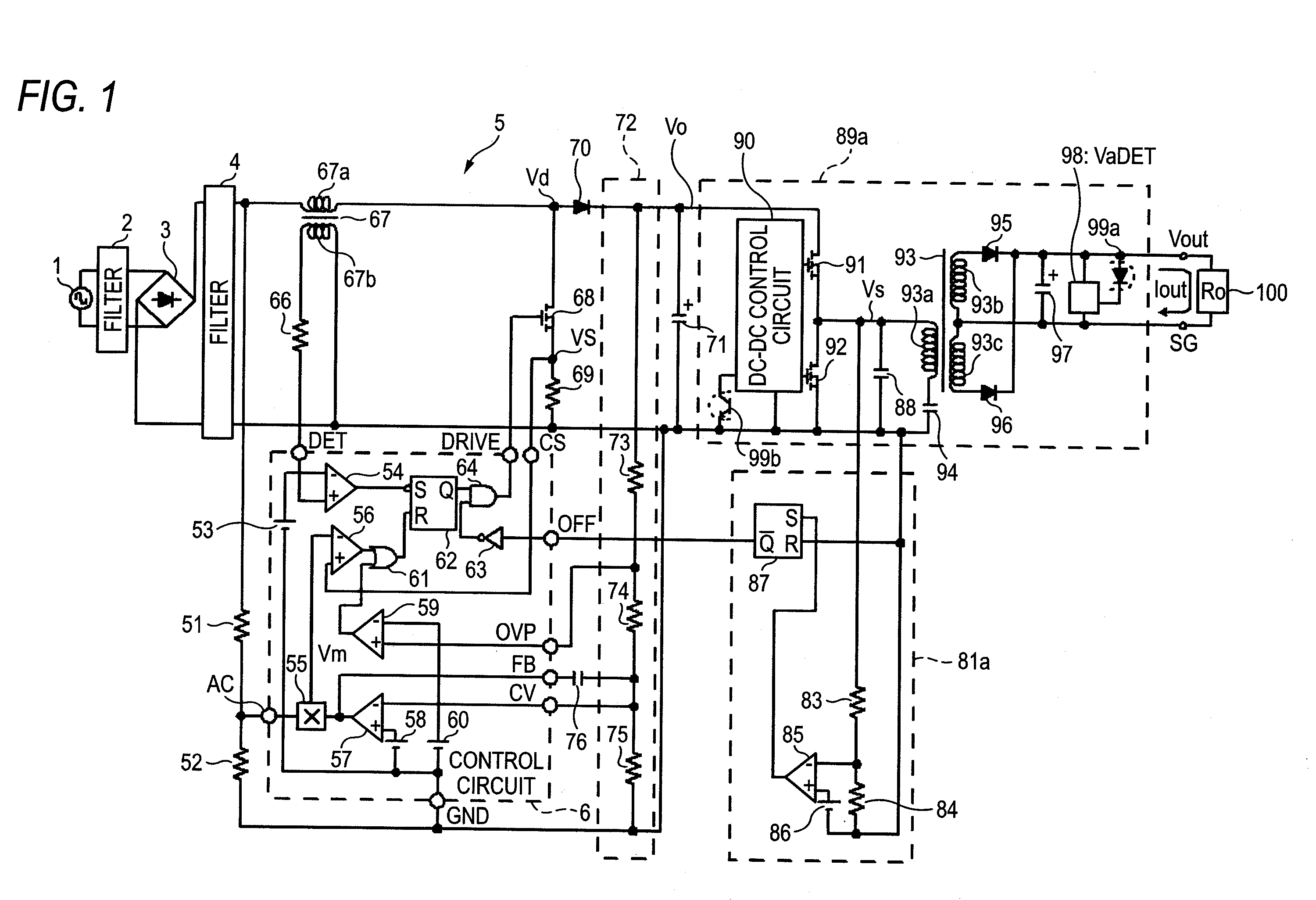
FIG. 1 is a diagram of a direct current power source circuit including a power factor improvement circuit according to an exemplary embodiment of the invention. In an over-voltage protection circuit 81, which functions as a latch-type output over-voltage detection circuit, of a power factor improvement circuit according to the exemplary embodiment, an over-voltage detection terminal (positive terminal) of the over-voltage protection circuit 81 is connected to a connection point of switching elements 91, 92 of a DC-DC converter 89a. Incidentally, an over-voltage detection terminal (negative terminal) of the over-voltage protection circuit 81 is connected to a line common to the ground GND terminal of the power factor improvement circuit.

The power factor improvement circuit 5 having the over-voltage protection circuit shown in FIG. 1 has a structure in which the DC-DC converter 89a is connected to an output of the power factor improvement circuit 5. A structure of the power factor imp...


PUM


Abstract

An over-voltage protection circuit of the invention is connected with a DC-DC converter having a structure in which a plurality of switching elements is serially connected to a direct current output voltage terminal of a power factor improvement circuit. An output over-voltage detection resistance of a latch-type output over-voltage detection circuit is connected to a connection point at which the plurality of switching elements is connected.

Description

CROSS REFERENCE TO RELATED APPLICATIONSThis application claims priority from Japanese Patent Application No. 2009-200055 filed on Aug. 31, 2009, the entire subject matter of which is incorporated herein by reference.BACKGROUND OF THE INVENTION1. Field of the InventionThe present invention relates to a protection circuit of a power factor improvement circuit.2. Description of the Related ArtFIG. 4 shows one example of a related-art power factor improvement circuit. In FIG. 4, a sinusoidal voltage from an alternating power source 1 passes through a filter 2 and is full wave-rectified in a full-wave rectification circuit 3. Then, the rectified full-wave passes through a filter 4 and then is supplied to a power factor improvement circuit 5. The power factor improvement circuit 5 is a voltage step up active filter type including a main coil 67a of a choke coil 67, a switching element 68, a diode 70 and an output condenser 71. The power factor improvement circuit 5 includes a control circ...

Claims


Application Information

Patent Timeline
Patent Type & Authority Applications(United States)
IPC IPC(8): H02M3/335
CPCH02M1/4225Y02B70/126H02M3/337Y02B70/10H02M3/33571H02M3/01
Inventor NAKAMURA, TETSUYAKAMINAGA, YUKIHIRO
Owner SANKEN ELECTRIC CO LTD
Why Eureka
Try Eureka