Drive control device for an electric load

a technology of driving control and electric load, which is applied in the direction of power supply testing, instruments, pulse techniques, etc., can solve the problems of inability to accurately detect abnormalities, heavy load imposed by the control on the monitoring/controlling side, etc., and achieve accurate determination processing, reduce load, and increase the effect of control safety

Active Publication Date: 2011-06-09
MITSUBISHI ELECTRIC CORP
View PDF2 Cites 28 Cited by
  • Summary
  • Abstract
  • Description
  • Claims
  • Application Information

AI Technical Summary

Benefits of technology

[0018]According to the present invention, the state storing circuit for collating the control output signal directed to the switching element and an open or closed-circuit state of the switching element to each other, thereby generating the closed-circuit determination storing signal and the open-circuit determination storing signal, is provided, and the monitoring / controlling means periodically reads the determination storing signals, thereby comprehensively determining presence / absence of an abnormality, and the state storing circuit is periodically reset. Thus, even for a circuit closing command signal or circuit opening command signal in a short period, a determination result whether the switching element has normally closed or opened is stored, and thus can be read at a time delayed from a generated timing of the circuit closing command signal or circuit opening command signal, resulting in a reduction of the load relating to the quick response imposed on the switching control means, and effects of surely detecting presence / absence of an abnormality generation, and increasing safety of the control. Further, when the circuit closing command signal and the circuit opening command signal change relatively slowly, and only the closed-circuit or open-circuit determination storing signal is read by the read operation for the present time, and the open-circuit or closed-circuit determination storing signal is read by the read operation for the subsequent time, there is provided an effect that, by considering together the closed-circuit determination storing signal and the open-circuit determination storing signal, presence / absence of an abnormality can be determined. Further, the determination storing circuit repeats the determination operation while the determination storing circuit is periodically reset, and thus an incorrect storing state due to a malfunction caused by noises or the like does not remain, and accurate determination processing can be carried out.

Problems solved by technology

As a result, though the apparatus is characterized in that the circuit scale on the switching element side is small, a heavy load resulting from the control is imposed on the monitoring / controlling means side.
A first problem thereof is that, for example, when, to a switching element opening / closing highly frequently by a pulse-width modulation signal, a circuit opening command or a circuit closing command in an extremely short period is given, in the short period in which this circuit opening command or circuit closing command is being fed, the state detection signal must be read immediately.
A second problem thereof is that, for an electric load to which the opening / closing operation is rarely carried out, when the command directed to the switching element changes from the circuit opening command or circuit closing command to the circuit closing command or circuit opening command, it is necessary to always provide monitoring in order not to miss the states before and after the command change.
Further, for example, when one monitoring / controlling means including a microprocessor is providing a large number of switching elements with the monitoring / controlling, or a serial communication line is used in order to reduce signal lines used for a large number of switching elements, a response relating to the monitoring / controlling is especially important subject, and a problem that an accurate abnormality detection cannot be carried out arises.

Method used


Image

  • Drive control device for an electric load
  • Drive control device for an electric load
  • Drive control device for an electric load

Examples


first embodiment

(3) Essential Points and Characteristics of First Embodiment

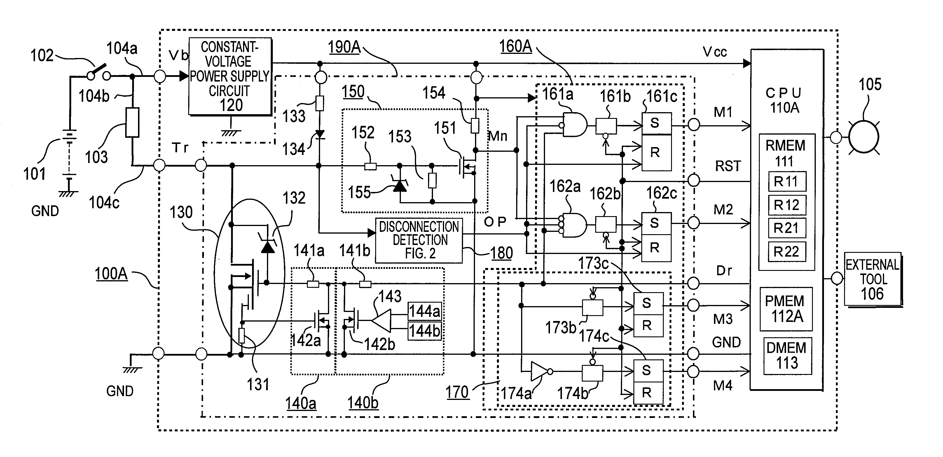
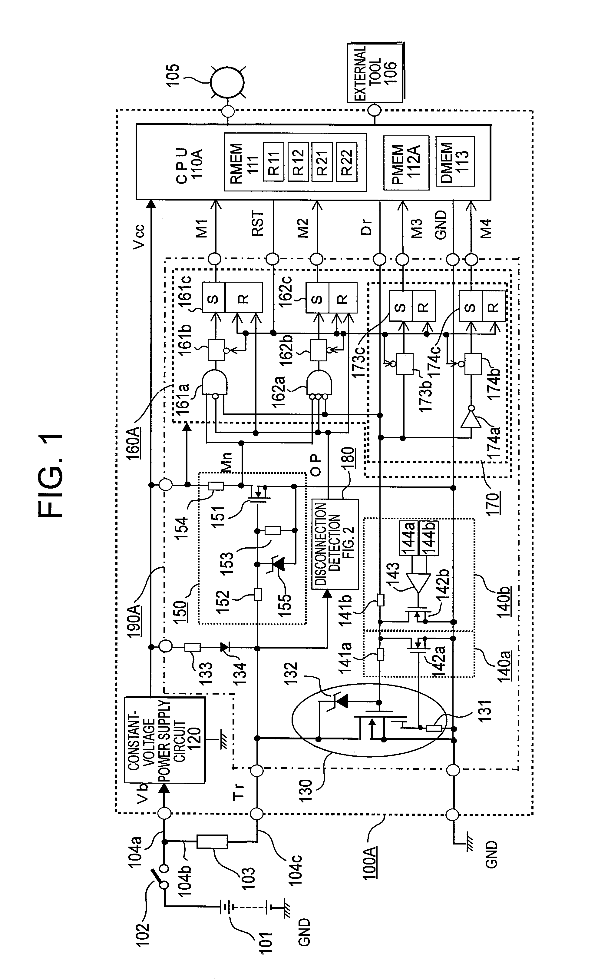
[0086]As apparent from the above description, the drive control device for an electric load according to the first embodiment is the drive control device 100A for an electric load including the switching element 130 serially connected to the electric load 103 to which the power is supplied from the drive power source 101, and the monitoring / controlling means 110A for performing the opening / closing control of the switching element 130, and monitoring presence / absence of an abnormal state of the power supply circuit for the electric load 103, the monitoring / controlling means 110A generates the control output signal Dr serving as the circuit closing command or the circuit opening command directed to the switching element 130, and supplies the switching element 130 and the determination storing circuit 160A with the control output signal, the switching element 130 generates the state detection signal Mn according to open / closed...

second embodiment

(3) Essential Points and Characteristics of Second Embodiment

[0114]As apparent from the above description, the drive control device for an electric load according to the second embodiment is the drive control device for an electric load 100B including the switching element 130 serially connected to the electric load 103 to which the power is supplied from the drive power source 101, and the monitoring / controlling means 1108 for performing the opening / closing control of the switching element 130, and monitoring presence / absence of an abnormal state of the power supply circuit for the electric load 103. The monitoring / controlling means 1108 generates the control output signal Dr serving as the circuit closing command or the circuit opening command directed to the switching element 130, and supplies the switching element 130 and the determination storing circuit 160B with the control output signal Dr. The switching element 130 generates the state detection signal Mn according to open / c...

third embodiment

(3) Essential Points and Characteristics of Third Embodiment

[0130]As apparent from the above description, the drive control device for an electric load according to the third embodiment is the drive control device for an electric load 100C including the switching element 130 serially connected to the electric load 103 to which the power is supplied from the drive power source 101, and the monitoring / controlling means 110C for performing the opening / closing control of the switching element 130, and monitoring presence / absence of an abnormal state of the power supply circuit for the electric load 103. The monitoring / controlling means 110C generates the control output signal Dr serving as the circuit closing command or the circuit opening command directed to the switching element 130, and supplies the switching element 130 and the determination storing circuit 160C with the control output signal Dr. The switching element 130 generates the state detection signals Mn and OC according to ...


PUM


Abstract

Provided is a drive control device capable of surely detecting, by a monitoring / controlling unit, an abnormality of a short circuit and a disconnection in a power supply circuit to an electric load, and of decreasing a load required for a quick response imposed on the monitoring / controlling unit. A switching element is controlled to open / close by a control output signal generated by a monitoring / controlling unit, and a determination storing circuit determines whether circuit opening and circuit closing have been correctly carried out and stores a result of the determination, and periodically reports to the monitoring / controlling unit. While the stored content of the determination is periodically reset, the determination operation is updated and continues. The monitoring / controlling unit does not need to immediately monitor the determination storing signal when the open / closing command is generated.

Description

BACKGROUND OF THE INVENTION[0001]1. Field of the Invention[0002]The present invention relates to a drive control device for an electric load including a switching element serially connected to an electric load to which a power is supplied from a drive power source, and monitoring / controlling means for performing opening / closing control of the switching element, and monitoring presence / absence of an abnormal state of a power supply circuit for the electric load, and more particularly, to a drive control device for an electric load improved so as not to miss whether a switching element is correctly brought into a closed-circuit state or an open-circuit state according to a momentary circuit closing command or circuit opening command, or a change in the command from the circuit closing command to the circuit opening command or the circuit opening command to the circuit closing command thereby surely detecting presence / absence of an abnormal state.[0003]2. Description of the Related Art...

Claims


Application Information

Patent Timeline
Patent Type & Authority Applications(United States)
IPC IPC(8): G05F1/10G01R31/50
CPCG01R31/024G01R31/42H03K2017/0806H03K17/18H03K17/0822G01R31/50
Inventor ZUSHI, YUJISUZUKI, SHINSUKEISHII, AKIHIKO
Owner MITSUBISHI ELECTRIC CORP
Why Eureka
Try Eureka