Image display device, brightness control method and brightness control program

a technology of brightness control and image display, which is applied in the direction of camera body details, television systems, instruments, etc., can solve the problems of user dizziness, particularly problematic 33701, and user disorientation of thefinder image, so as to reduce or eliminate the disorientation of the user

Active Publication Date: 2011-08-18
ADVANCED INTERCONNECT SYST LTD
View PDF11 Cites 7 Cited by
  • Summary
  • Abstract
  • Description
  • Claims
  • Application Information

AI Technical Summary

Benefits of technology

[0007]An advantage of some aspects of the invention is to provide an image display device, a brightness control method, and a brightness control program, capable of reducing or eliminating disorientation of a user who views images displayed on a display unit.

Problems solved by technology

In the DSC mounted with the EVF, finder image disorientation as disclosed in JP-A-2007-33701 is particularly problematic.
In other words, when a user continues to view images displayed on the liquid crystal screen through the EVF, the user feels dizzy, seems to feel disorientated, or feels an unpleasant pressure behind the eye.
In addition, the EVF mounted in the DSC until now is relatively low in terms of the luminance of the liquid crystal screen or the resolution, and thus a user hardly feels “disorientated” as described above.
However, hereafter, as a user uses the EVF more and more and luminance and definition of the EVF are increased, it is thought that the generation of the “disorientation” of a user is further problematic.

Method used


Image

  • Image display device, brightness control method and brightness control program
  • Image display device, brightness control method and brightness control program
  • Image display device, brightness control method and brightness control program

Examples


first embodiment

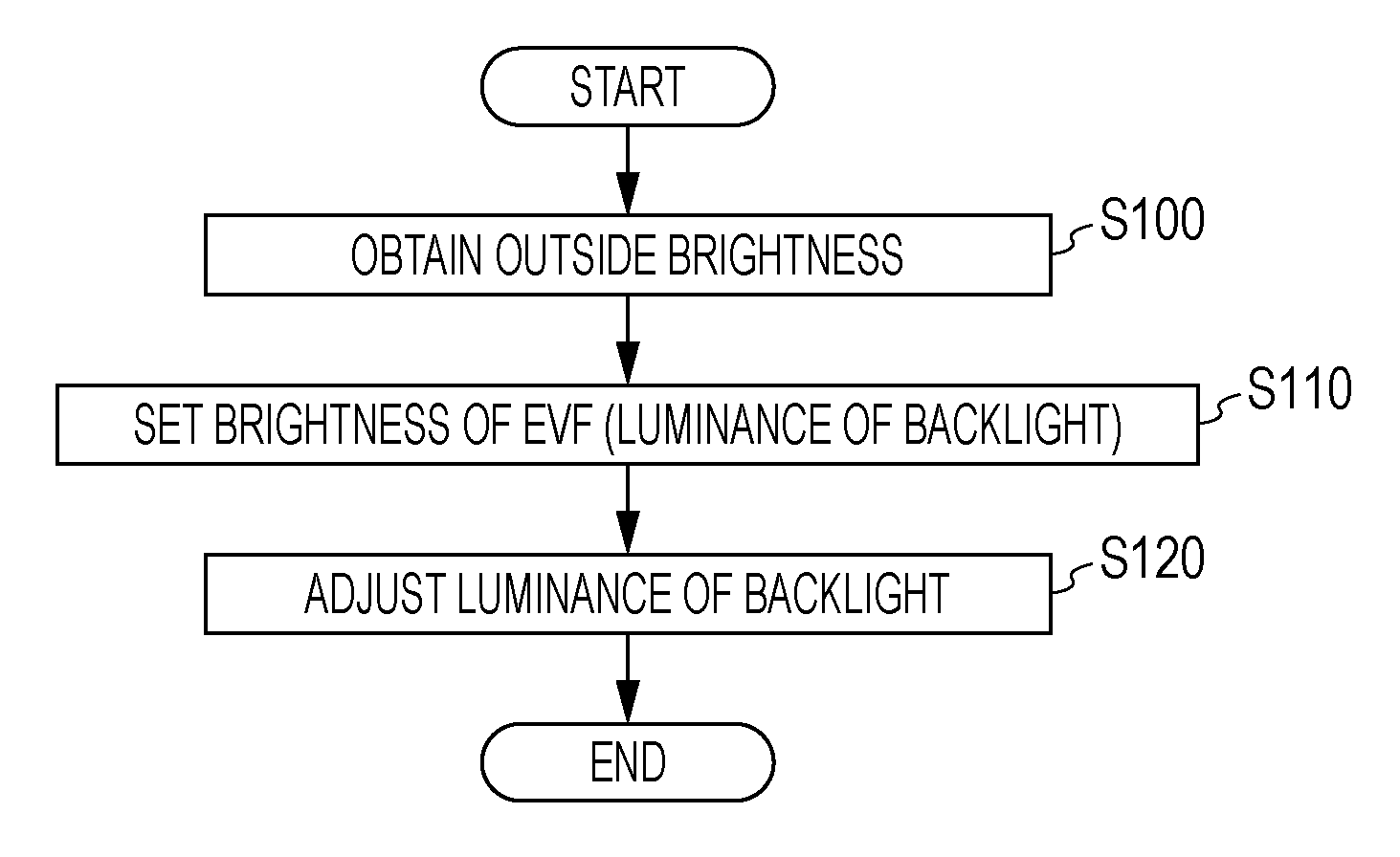
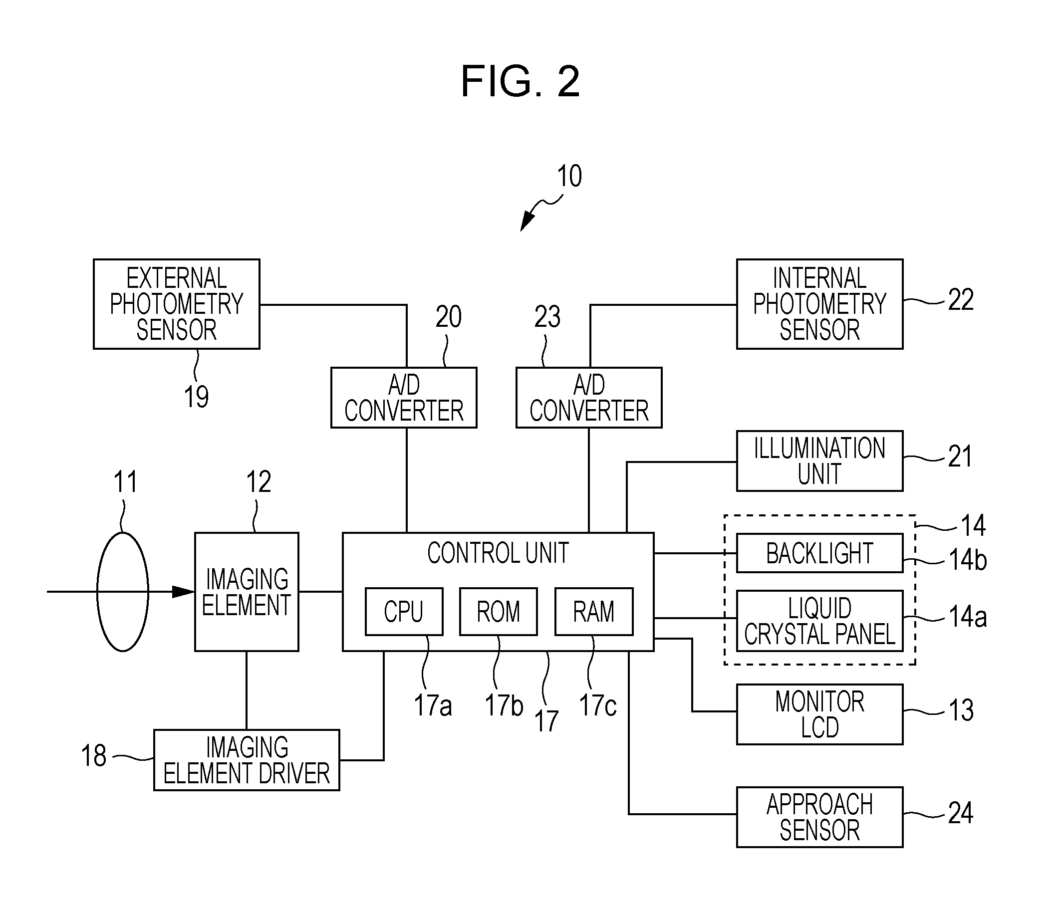
[0035]FIG. 4 shows a brightness control process mainly performed by the control unit 17 when the EVF 14 is made to display images based on the digital image data and is a flowchart illustrating a process according to the first embodiment. First, in step S100, the control unit 17 obtains the brightness of the outside of the DSC 10 by driving the external photometry sensor 19. In other words, the control unit 17 makes the external photometry sensor 19 measure the light amount of the outside and obtains an output signal as a result of the measurement via the A / D converter 20.

[0036]In step S110, the control unit 17 sets brightness of the EVF 14 according to the brightness of the outside of the DSC 10 obtained in step S100. The brightness of the EVF 14 set here indicates a luminance of the backlight 14b. In this case, the higher the level of the light amount indicated by the measured result (that is, as the outside of the DSC 10 becomes brighter), the higher the luminance set by the cont...

second embodiment

[0043]FIG. 8 shows a brightness control process mainly performed by the control unit 17 when the EVF 14 is made to display images based on the digital image data and is a flowchart illustrating a process according to the second embodiment. First, in step S200, the control unit 17 obtains brightness of the inside of the finder box FB by driving the internal photometry sensor 22. In other words, the control unit 17 makes the internal photometry sensor 22 measure a light amount and obtains an output signal as a result of the measurement via the A / D converter 23.

[0044]In step S210, the control unit 17 sets brightness of the EVF 14 according to the brightness of the inside of the finder box FB obtained in step S200. The brightness of the EVF 14 set here indicates a luminance of the backlight 14b. In this case, the control unit 17 sets a high luminance to the extent that the level of the light amount indicated by the result measured in step S200 is high (that is, as the inside of the find...

third embodiment

[0046]FIG. 9 shows a brightness control process mainly performed by the control unit 17 when the EVF 14 is made to display images based on the digital image data and is a flowchart illustrating a process according to the third embodiment. First, in step S300, the control unit 17 obtains the brightness of the EVF 14. In this case, the control unit 17 can obtain the brightness of the EVF 14 based on any one or both of the digital image data generated and output by the imaging element 12 and the brightness of the backlight 14b. For example, an average luminance for the digital image data is calculated and the calculated average luminance is designated as brightness of the EVF 14. Alternatively, a luminance indicated by a parameter set as indicating a luminance of the backlight 14b by the control unit 17 is designated as brightness of the EVF 14.

[0047]However, here, the control unit 17 obtains the brightness of the EVF 14 based both the digital image data and the brightness of the backl...


PUM


Abstract

An image display device includes a display unit that is installed inside a finder window provided in a housing and displays images, an illumination unit that illuminates a space inside the finder window, and a control unit that when brightness of the display unit is a first brightness, sets the brightness of the illumination unit to a second brightness, and when the brightness of the display unit is a third brightness brighter than the first brightness, sets the brightness of the illumination unit to a fourth brightness brighter than the second brightness.

Description

BACKGROUND[0001]1. Technical Field[0002]The present invention relates to an image display device, a brightness control method, and a brightness control program.[0003]2. Related Art[0004]As a digital still camera (DSC), there is known one mounted with an optical finder (see JP-A-2007-33701). Also, instead of the optical finder, there is known a DSC mounted with an electronic view finder (hereinafter, referred to as an “EVF”). The EVF displays image data generated by an imaging element of the DSC on a liquid crystal screen installed in an inner space of a finder window of the finder.[0005]In the DSC mounted with the EVF, finder image disorientation as disclosed in JP-A-2007-33701 is particularly problematic. In other words, when a user continues to view images displayed on the liquid crystal screen through the EVF, the user feels dizzy, seems to feel disorientated, or feels an unpleasant pressure behind the eye. This dizziness, disorientation or discomfort (hereinafter, collectively r...

Claims


Application Information

Patent Timeline
Patent Type & Authority Applications(United States)
IPC IPC(8): G03B17/20
CPCH04N5/58H04N5/23293G09G3/3406
Inventor ICHIKAWA, TATSUYA
Owner ADVANCED INTERCONNECT SYST LTD
Why Eureka
Try Eureka