Non-contact medical thermometer with stray radiation shielding

a radiation shielding and thermometer technology, applied in the field of non-contact infrared thermometers, can solve the problems of affecting the measurement accuracy of the thermometer, etc., and achieves the effect of high emissivity

Inactive Publication Date: 2011-09-22
HELEN OF TROY LIMITED
View PDF22 Cites 112 Cited by
  • Summary
  • Abstract
  • Description
  • Claims
  • Application Information

AI Technical Summary

Benefits of technology

[0017]A non-contact infrared (IR) thermometer according to the present invention includes an IR radiation sensor thermally coupled to a heating element and a thermal shield having an interior surface positioned within the sensor's field of view, such interior surface has a high emissivity. An electronic circuit controlling the heating element maintains the temperatures of the sensor and shield substantially close to an anticipated surface

Problems solved by technology

Practically, these temperatures may differ as the result of error.
The second summand can be more problematic, especially due to a generally unknown and unpredictable value of the object's emissivity εb,.
IR radiation from stray objects alters the measured flux, and t

Method used


Image

  • Non-contact medical thermometer with stray radiation shielding
  • Non-contact medical thermometer with stray radiation shielding
  • Non-contact medical thermometer with stray radiation shielding

Examples


Embodiment Construction

:

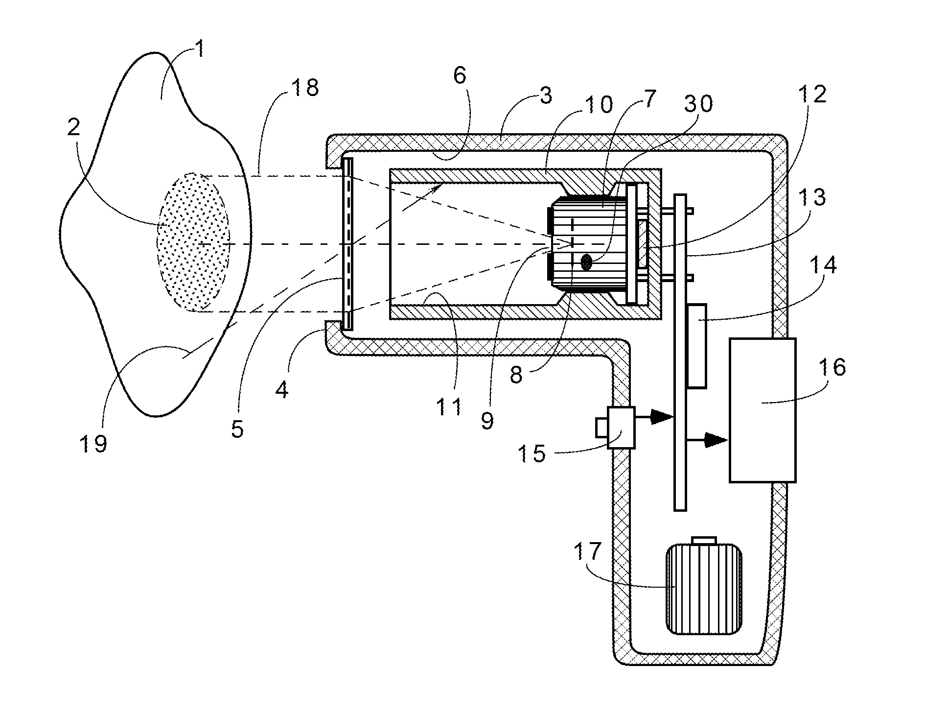
[0033]An IR thermometer is disclosed that includes a thermal shield having a surface that is covered by the sensor's field of view. The surface preferably includes a high-emissivity coating that minimizes stray radiation from the shield. For the purpose of illustrating principles of the present invention, several non-limiting embodiments of the IR thermometer and thermal shield are described below. Accordingly, the invention is to be limited only by the scope of the claims and their equivalents.

[0034]FIG. 1 shows a schematic, cross-sectional View of a remote thermometer. The thermometer of FIG. 1 includes a housing 3 that contains an infrared sensor 7, several optical components which are described further herein, a circuit board 13 with an electronic circuit 14, a power supply 17, a control button 15, and a display 16. The optical components include an aperture 9 that admits IR radiation into the sensor 7, a lens 5 and a thermal shield 10. The sensor 7 may also preferably contain ...


PUM


Abstract

A non-contact infrared (IR) thermometer for measuring temperature from the surface of an object includes an IR radiation sensor attached to a heating element and a thermal shield having an interior surface positioned within the sensor's field of view that has a high emissivity. An electronic circuit controlling the heating element maintains the temperatures of the sensor and shield substantially close to an anticipated surface temperature of the object. The IR radiation sensor is further thermally coupled to a reference temperature sensor. An optical system positioned in front of the shield focuses thermal radiation from the object on the surface of the sensor, while the shield prevents stray radiation from reaching the sensor. Signals from the IR and reference sensors are used to calculate the object's surface temperature.

Description

[0001]This application is a national phase application under §371 of PCT / US2009 / 61842, filed Oct. 23, 2009, which claims priority to Provisional Patent Application No. 61 / 197,023, filed Oct. 23, 2008, the entire content of which is expressly incorporated herein by reference.FIELD OF THE INVENTION[0002]The present invention relates to devices for measuring temperature, and more specifically, to non-contact infrared thermometers for medical applications incorporating shielding to reduce the effects of stray radiation.BACKGROUND OF THE INVENTION[0003]A thermal radiation or infrared (IR) thermometer is a device capable of measuring temperature without physically contacting the object of measurement. Thus, such thermometers are often called “non-contact” or “remote” thermometers. In an IR thermometer, the temperature of an object is taken by detecting an intensity of the IR radiation which is naturally emanated from the object's surface. For objects between 0 and 100° C., this requires t...

Claims


Application Information

Patent Timeline
IPC IPC(8): G01J5/08G01J5/02
CPCG01J5/0011G01J5/061G01J5/08G01J5/0896G01J5/0809G01J5/0834G01J5/089G01J5/0806G01J5/0808G01J5/0804G01J5/07G01J5/00A61B5/01G01J5/02
Inventor FRADEN, JACOB
Owner HELEN OF TROY LIMITED
Why Eureka
Try Eureka