Emergency services for voice over IP telephony (E-VoIP)

a voice over internet protocol and emergency services technology, applied in the field of emergency services for voice over internet protocol telephony systems, can solve the problems of not being able to determine the user's location, 911 operator will not be able to transmit location, and the implementation of emergency services in the voip telephony system is not as reliabl

a voice over internet protocol and emergency services technology, applied in the field of emergency services for voice over internet protocol telephony systems, can solve the problems of not being able to determine the user's location, 911 operator will not be able to transmit location, and the implementation of emergency services in the voip telephony system is not as reliabl

US20110263219A1Active Publication Date: 2011-10-27HASENFANG DENNIS J +1

Image

  • Emergency services for voice over IP telephony (E-VoIP)
  • Emergency services for voice over IP telephony (E-VoIP)
  • Emergency services for voice over IP telephony (E-VoIP)

Examples


Embodiment Construction

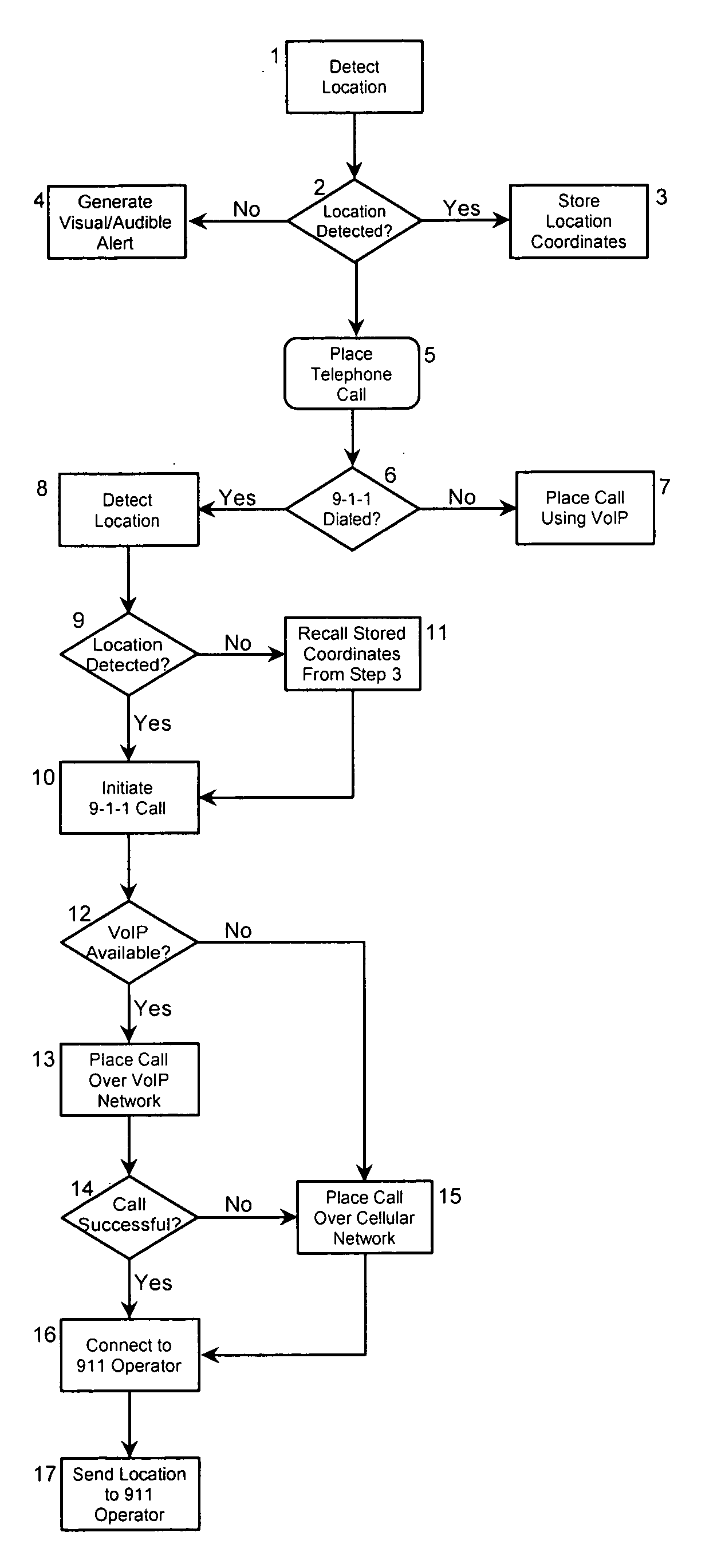
[0016]The present invention is directed to a system for providing emergency services to users of VoIP phones or other types of VoIP telephony devices (the “E-VoIP system”). In accordance with a first embodiment of the invention, the E-VoIP system employs GPS or cellular technology to determine the physical coordinates of the VoIP phone. When a caller uses the VoIP phone to dial an emergency number, such as 9-1-1, the E-VoIP system transmits the physical coordinates of the VoIP phone to an Emergency Services 911 Call Center, which is also referred to as a Public Safety Answering Point (“PSAP”). Thus, the 911 operator is able to locate the caller wherever the VoIP phone is being used.

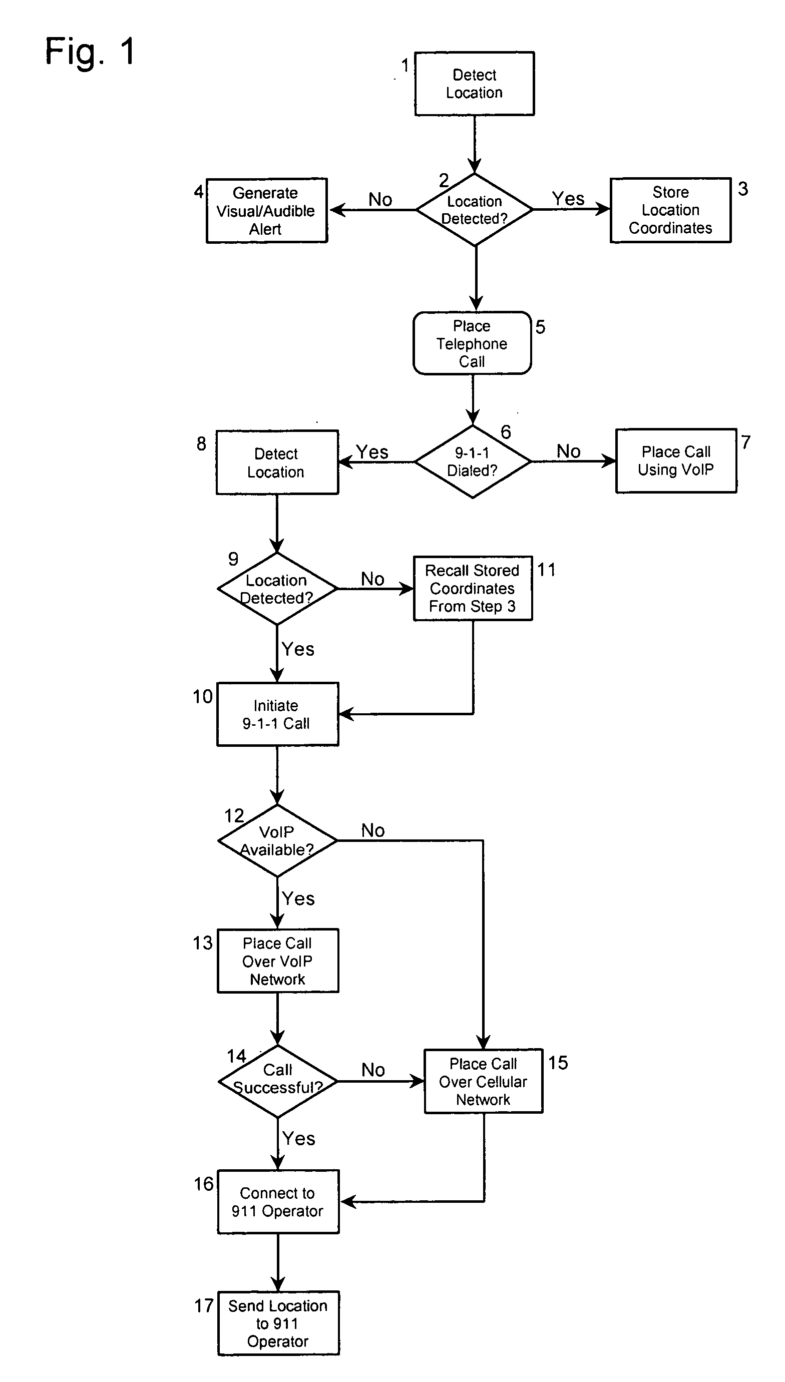
[0017]The operation of one embodiment of the E-VoIP system of the present invention in the context of a residential setting is illustrated schematically in FIG. 1. The E-VoIP system employs either conventional GPS tracking technology or, for example, CDMA or GSM cellular technology, to determine the physi...


PUM


Abstract

A method for determining the physical location of a VoIP phone and transmitting the physical location to an emergency services call center or the like comprises the steps of determining the physical location of the VoIP phone using multiple location detection technologies, placing a call to an emergency services call center using the VoIP phone, and automatically transmitting the physical location of the VoIP phone to the emergency services call center.

Description

[0001]This application is a continuation-in-part of U.S. patent application Ser. No. 11 / 500,135 filed on Aug. 7, 2006, which is based on and claims priority from U.S. Provisional Patent Application No. 60 / 706,088 filed on Aug. 5, 2005.BACKGROUND OF THE INVENTION[0002]The present invention relates to voice over internet protocol (“VoIP”) telephony systems. More particularly, the invention relates to a system for providing emergency services to users of VoIP phones.[0003]The implementation of emergency services for users of the Plain Old Telephone System (“POTS”) is fairly straightforward. Each telephone in the POTS is identified with a single user and address. Thus, when a user dials 9-1-1, or any applicable emergency number, the user's name and address are automatically transmitted to the Emergency Services 911 Call Center and the 911 operator can dispatch the proper authorities to this address.[0004]In contrast, the implementation of Emergency services in VoIP telephony systems is ...

Claims


Application Information

Patent Timeline
27 Oct 2011
Publication
US20110263219A1
IPC
H04M11/04
CPC
H04L12/66; H04W76/007; H04M11/04; H04W76/50; H04M3/42348; H04M3/5116
Inventors
HASENFANG, DENNIS J.; WILLIS, CHRISTOPHER C.