Optical connector cleaning tool

Active Publication Date: 2012-01-26
THE FUJIKURA CABLE WORKS LTD
View PDF1 Cites 15 Cited by
  • Summary
  • Abstract
  • Description
  • Claims
  • Application Information

AI Technical Summary

Benefits of technology

[0025]Accordingly, it is possible to easily perform cleaning work even in a case where a sufficient working space cannot be secured.
[0026]In the optical connector cleaning tool described in the above (10), a direction in which the central axis of the supply reel and the central axis of the winding re

Problems solved by technology

When performing butt joint of an optical connector to an optical fiber or the like, if contamination or foreign material is attached to a joining end face, it causes damage at the time of connection and disconnection, an increase in tra

Method used


Image

  • Optical connector cleaning tool
  • Optical connector cleaning tool
  • Optical connector cleaning tool

Examples


Embodiment Construction

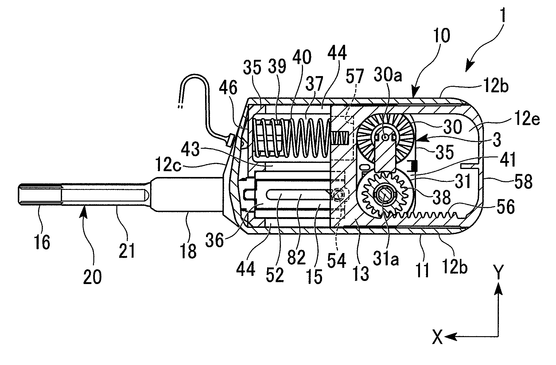
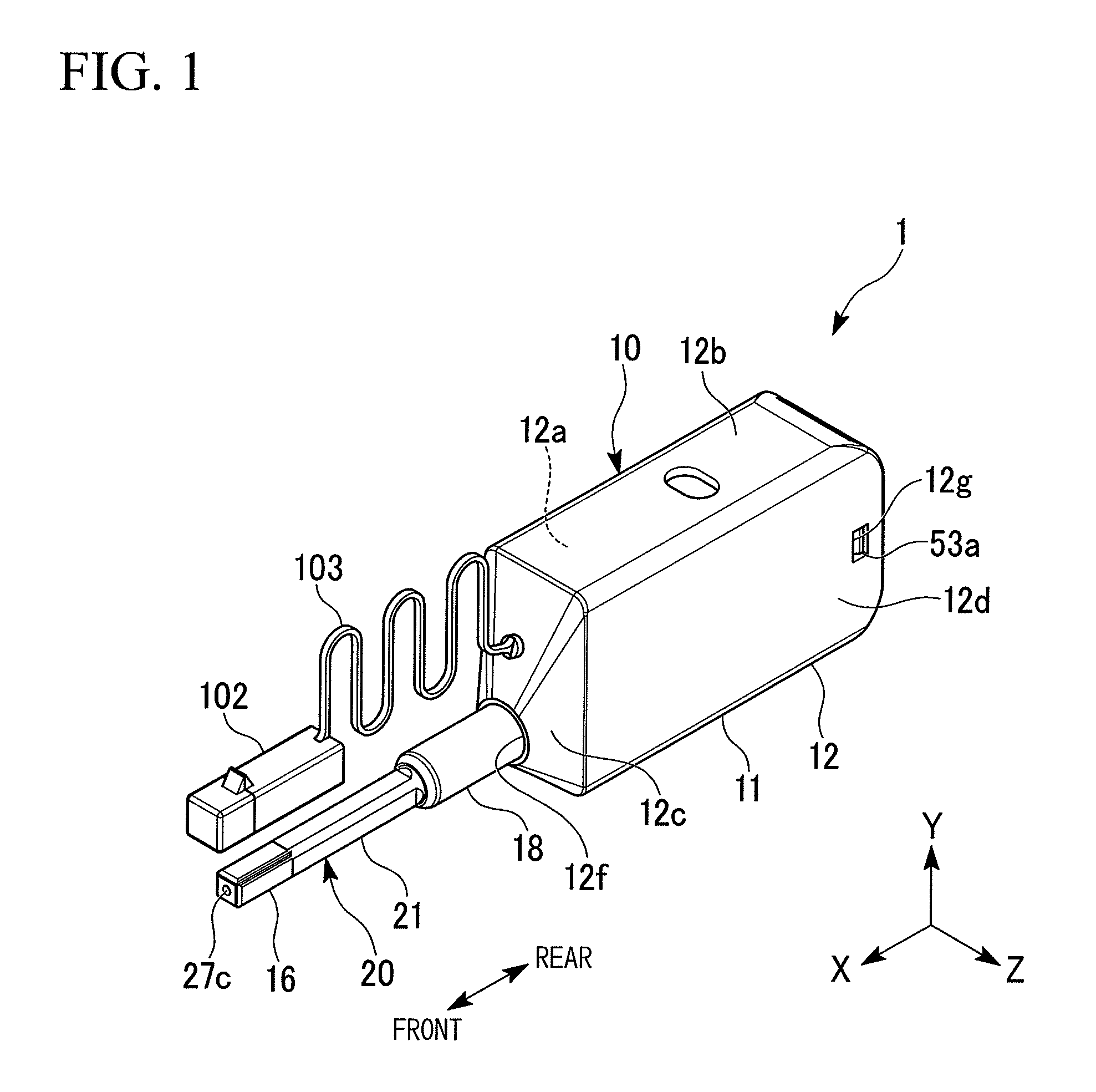
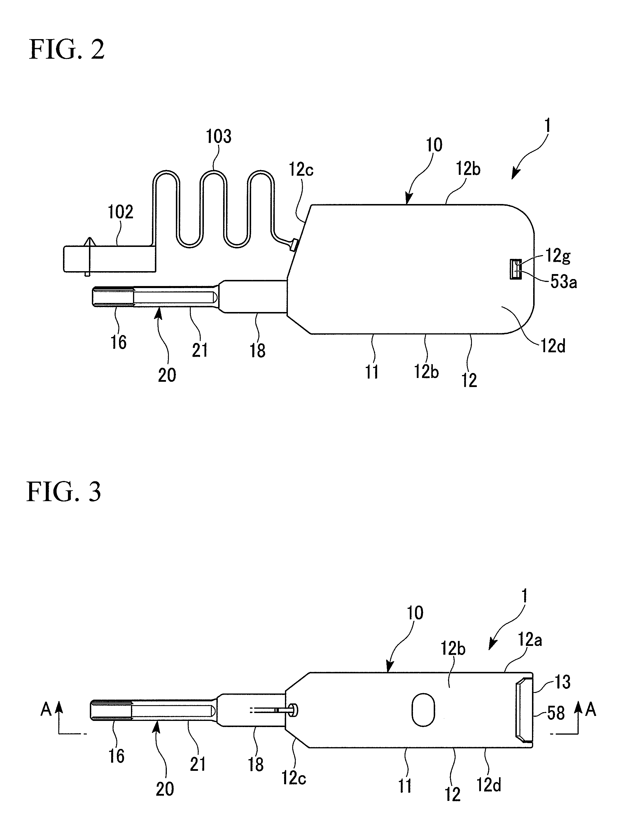
[0053]Hereinafter, an optical connector cleaning tool (hereinafter also simply referred to as a “cleaning tool”) 1 according to a first embodiment of the present invention will be described with reference to the drawings.

[0054]As shown in FIGS. 1 to 4, the cleaning tool 1 includes a tool main body 10 and an extension section 20 that extends from the tool main body 10.

[0055]In the following explanation, the leading end direction of the extension section 20 (an extension tube body 21) shown in FIG. 1 is sometimes referred to as the front in an extending direction or simply referred to as the front and the opposite direction is sometimes referred to as the rear.

[0056]Also, an XYZ orthogonal coordinate system shown in FIG. 1 is set and a positional relationship between the respective members is sometimes described referring to the coordinate system. The X direction is a direction (the front-and-back direction in FIG. 1) which follows the extension section 20, the Y direction is a width ...


PUM


Abstract

An optical connector cleaning tool according to the present invention includes a tool main body and an extension section that extends from the tool main body, wherein the tool main body includes a supply reel and a winding reel, which perform supply and take-up of the cleaning body, a housing body that houses the supply reel and the winding reel, and a biasing member that is located in the housing body and biases the housing body. The biasing member biases backward in the extending direction the housing body that is in a state where the housing body has relatively moved forward in the extending direction of the extension section, and a position in a front-and-back direction of the biasing member is close to the front compared to positions in a front-and-back direction of the supply reel and the winding reel.

Description

CROSS-REFERENCE TO RELATED APPLICATION[0001]This is a Continuation Application of International Application No. PCT / JP2011 / 050971, filed on Jan. 20, 2011, which claims priority to Japanese Patent Application No. 2010-049849 filed on Mar. 5, 2010 and Japanese Patent Application No. 2010-049850 filed on Mar. 5, 2010. The contents of the aforementioned applications are incorporated herein by reference.BACKGROUND OF THE INVENTION[0002]1. Field of the Invention[0003]The present invention relates to an optical connector cleaning tool that cleans a joining end face of an optical connector by a cleaning body such as a cloth.[0004]2. Description of the Related Art[0005]When performing butt joint of an optical connector to an optical fiber or the like, if contamination or foreign material is attached to a joining end face, it causes damage at the time of connection and disconnection, an increase in transmission loss, or the like. For this reason, it is necessary to clean the joining end face ...

Claims


Application Information

Patent Timeline
IPC IPC(8): B08B1/04
CPCG02B6/3866
Inventor FUJIWARA, KUNIHIKO
Owner THE FUJIKURA CABLE WORKS LTD
Why Eureka
Try Eureka