Display device and display control method

a display device and control method technology, applied in the field of display devices and display control methods, can solve the problems of inability to display images at an appropriate brightness, affecting the display effect, so as to reduce the visual unpleasant sensation

Active Publication Date: 2012-02-16
PANASONIC INTELLECTUAL PROPERTY MANAGEMENT CO LTD
View PDF2 Cites 21 Cited by
  • Summary
  • Abstract
  • Description
  • Claims
  • Application Information

AI Technical Summary

Benefits of technology

[0016]The present invention was devised in order to resolve the foregoing problems, and its object is to provide a display device and a display control method capable of reducing a visually unpleasant sensation that is experienced by a user.
[0019]According to the present invention, since the emission brightness of the respective light sources corresponding to each of the divided regions is determined in consideration of the characteristic amount of the image of the overall screen in addition to the characteristic amount of the image of each of the divided regions, it is possible to determine the emission brightness of the light sources so as to inhibit black floating and insufficient brightness, and reduce the visually unpleasant sensation that is experienced by the user.

Problems solved by technology

Moreover, when a display screen is divided into a plurality of regions and the brightness is changed for each segmented region, a visually unpleasant sensation will arise between the segmented regions.
Nevertheless, even if the foregoing technologies are adopted, when pixels (white pixels) of high brightness and pixels (black pixels) of low brightness coexist in the image to be displayed, there is a problem in that it is not possible to display the image at an appropriate brightness.
Nevertheless, it is difficult to cause the transmittance of the liquid crystal display element to become completely zero.
Thus, a gray image rather than a black image is displayed, and the so-called black floating problem will arise.
Nevertheless, in the region where the white image should be displayed, a gray image rather than a white image is displayed, and a problem of insufficient brightness will arise.

Method used


Image

  • Display device and display control method
  • Display device and display control method
  • Display device and display control method

Examples


embodiment 1

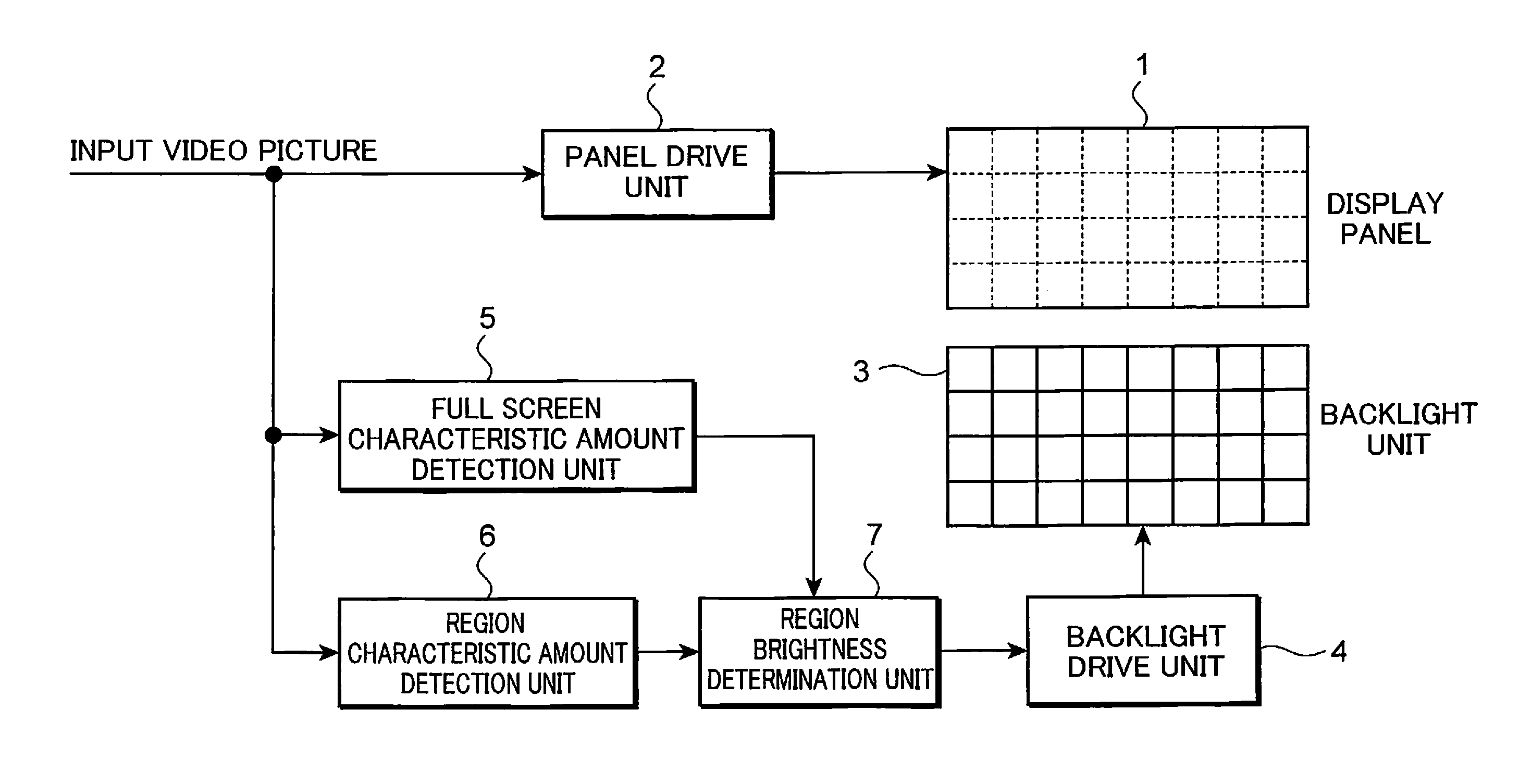
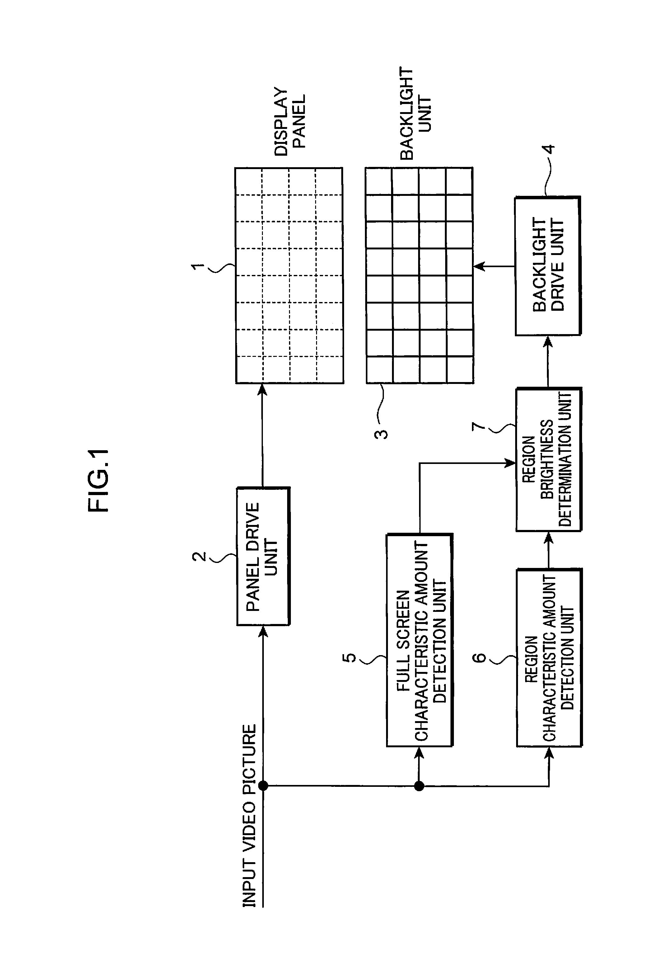
[0063]FIG. 1 is a block diagram showing the overall configuration of the display device in Embodiment 1 of the present invention. Foremost, the respective configurations of the display device of Embodiment 1 are explained in detail with reference to the block diagram of FIG. 1 showing the overall configuration of the display device of Embodiment 1. The display device of Embodiment 1 comprises a display panel 1, a panel drive unit 2, a backlight unit 3, a backlight drive unit 4, a full screen characteristic amount detection unit 5, a region characteristic amount detection unit 6, and a region brightness determination unit 7.

[0064]The display panel 1 is configured, for example, with a liquid crystal panel, and displays an input video picture. The panel drive unit 2 controls the drive of the display panel 1.

[0065]Although not shown, the display panel 1 comprises a plurality of gate wires, a plurality of source wires, a switching element, and a plurality of pixel cells, a plurality of p...

embodiment 2

[0194]The display device of Embodiment 2 according to the present invention is now explained. The difference with the display device of Embodiment 1 is that the display device further comprises a weight value storing unit which stores a predetermined weight value that changes according to the brightness, and that the region brightness determination unit 7 determines the emission brightness of the respective LEDs of the backlight unit 3 by multiplying the weight value stored in the weight value storing unit by a value that is detected by the region characteristic amount detection unit 6. Consequently, it is possible to set the emission brightness in further detail, inhibit the problem of black floating and insufficient brightness better than the processing method of Embodiment 1, and thereby provide a video picture to the user that will not cause a visually unpleasant sensation.

[0195]FIG. 18 is a block diagram showing the overall configuration of the display device in Embodiment 2 of...

embodiment 3

[0355]The display device of Embodiment 3 is now explained with reference to FIG. 1 and FIG. 36. Embodiment 3 is applied to cases of displaying a so-called letter box-type image in which a black strip image is displayed at the upper part and lower part of the screen as shown in FIG. 36A, or to cases of displaying a so-called side bar-type image in which a black strip image is displayed at the left side and right side of the screen as shown in FIG. 36B. FIG. 36A is a diagram showing an example of the screen on which a letter box-type image is displayed, and FIG. 36B is a diagram showing an example of the screen on which a side bar-type image is displayed.

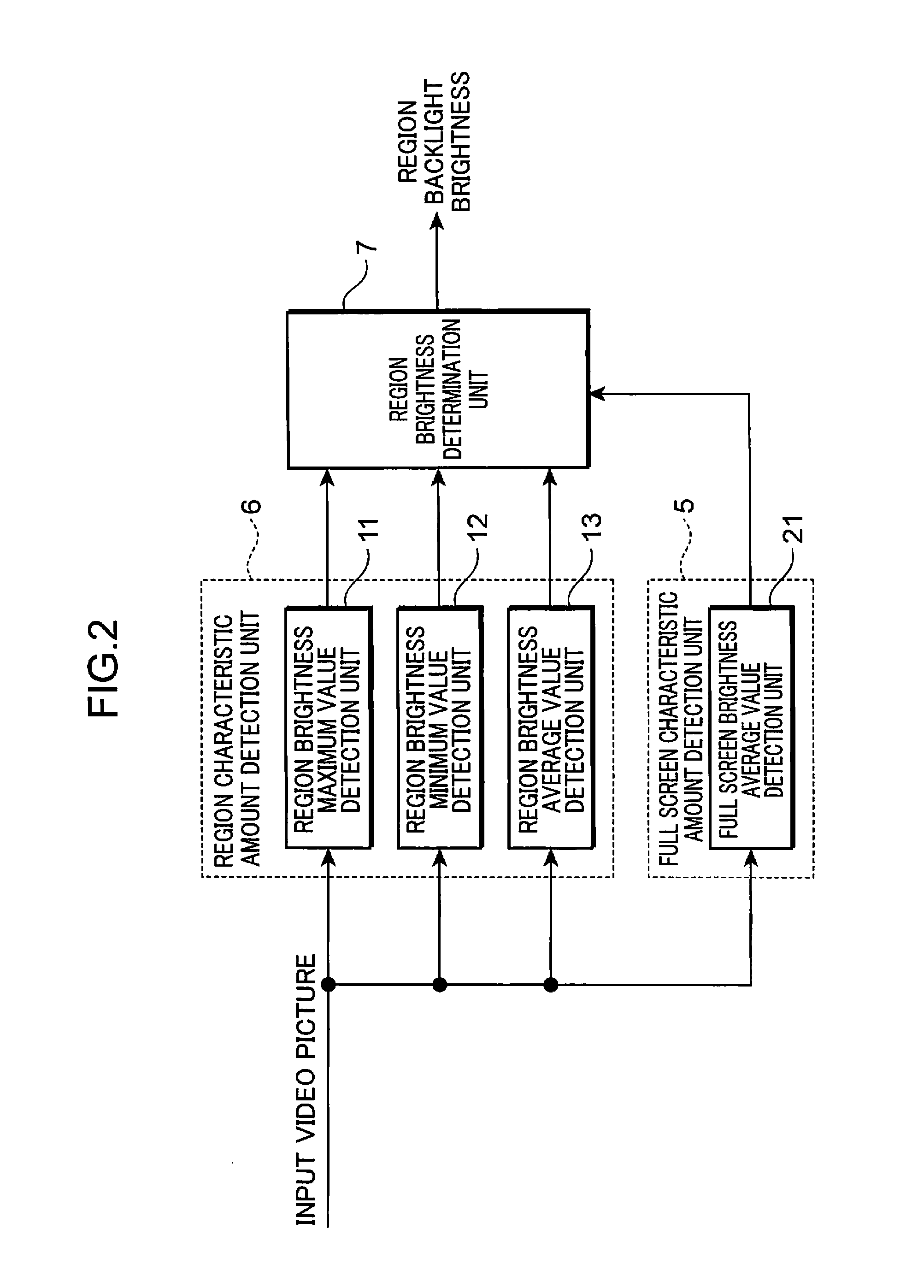
[0356]The foregoing full screen characteristic amount detection unit 5 detects, for the image of the overall screen displayed on the display panel 1, at least one among an average value of brightness, a maximum value of brightness, a minimum value of brightness, a low frequency component detection value (magnitude of low frequency com...


PUM


Abstract

Provided are a display device and a display control method capable of reducing a visually unpleasant sensation that is experienced by a user. This display device includes a display panel (1) which displays a video picture, a backlight unit (3) which is disposed on a back surface of the display panel (1), and which includes a plurality of light sources for each region obtained by dividing the display panel (1) into a plurality of regions, a region characteristic amount detection unit (6) which detects a characteristic amount of an image of each of the divided regions, a full screen characteristic amount detection unit (5) which detects a characteristic amount of an image of the overall display panel, a region brightness determination unit (7) which determines an emission brightness of the respective light sources corresponding to each of the regions based on the detected characteristic amount of the image of each region, and the detected characteristic amount of the image of the overall display panel, and a backlight drive unit (4) which drives the respective light sources to emit light at the determined emission brightness.

Description

TECHNICAL FIELD[0001]The present invention relates to a display device comprising a plurality of light sources on a back surface of a display panel, and a display control method for controlling a plurality of light sources disposed on a back surface of a display panel.BACKGROUND ART[0002]In a conventional display device, known is technology of dividing a display screen into a plurality of regions and changing the brightness for each segmented region in order to improve the picture quality of the display panel (for example, refer to Patent Literatures 1 and 2).[0003]Moreover, when a display screen is divided into a plurality of regions and the brightness is changed for each segmented region, a visually unpleasant sensation will arise between the segmented regions. With a conventional display device, in order to alleviate the visually unpleasant sensation between the segmented regions, known is technology of inhibiting the brightness difference between the target segmented region and ...

Claims


Application Information

Patent Timeline
Patent Type & Authority Applications(United States)
IPC IPC(8): G09G5/10
CPCG09G3/3426G09G2320/0646G09G2360/16
Inventor NAKANISHI, HIROKAZUNAKANISHI, ATSUSHI
Owner PANASONIC INTELLECTUAL PROPERTY MANAGEMENT CO LTD
Why Eureka
Try Eureka