Vehicle braking control device

a control device and brake pedal technology, applied in the direction of brake action initiation, brake system, transportation and packaging, etc., can solve the problems of driver unpleasant feeling, braking (generated braking force), and master-cylinder pressure generated by operating the brake pedal not being directly monitored, so as to reduce the unpleasant sensation for the driver

Active Publication Date: 2016-09-27
NISSAN MOTOR CO LTD
View PDF8 Cites 3 Cited by
  • Summary
  • Abstract
  • Description
  • Claims
  • Application Information

AI Technical Summary

Benefits of technology

[0018]Also, the control means, when the characteristic representing the relationship between the estimated amount of fluid consumed by braking and the actual master-cylinder pressure has a difference with regard to the reference map, sets a target value for the degree of relative displacement between the input member and the assist member based on the operating amount of the brake pedal, and corrects the degree of relative displacement between the input member and the assist member toward a direction to reduce characteristics differences, when controlling the force-multiplying actuator so that the degree of relative displacement matches the target value.
[0021]Also, by correcting the target value of the degree of relative displacement, the actual master-cylinder pressure becomes an ideal master-cylinder pressure (a reference master-cylinder pressure) with regard to the operating amount of the brake pedal, thereby controlling to vary the braking and pedal feel with regard to the assumption. This results in reducing an unpleasant sensation for the driver.

Problems solved by technology

However, with the conventional vehicle braking control device, when varying the relative displacement of the input member and the assist member, the master-cylinder pressure generated by operating the brake pedal is not directly monitored.
For that reason, there is a problem in that braking (generated braking force) and the feeling of the pedal will vary relative to preset assumptions, if the electric actuator is controlled based on the degree of relative displacement between the input member and the assist member or the displacement amount of the assist member.
Also, if the braking effectiveness and the brake feeling vary, the driver may experience an unpleasant feeling.

Method used


Image

  • Vehicle braking control device
  • Vehicle braking control device
  • Vehicle braking control device

Examples


embodiment 1

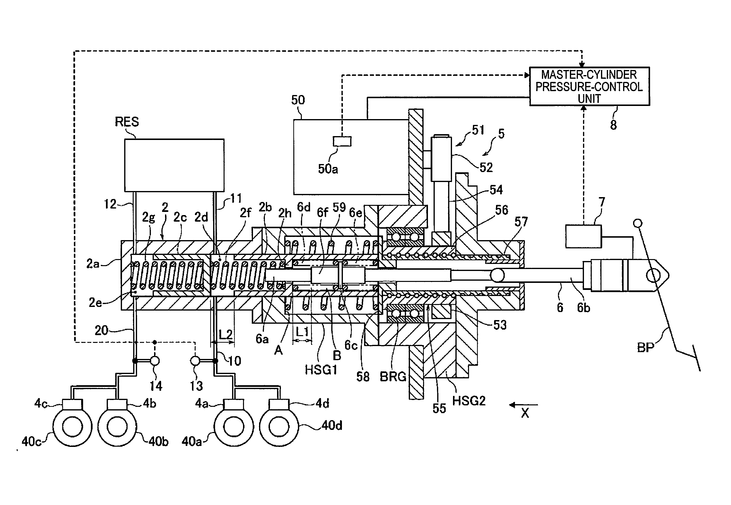
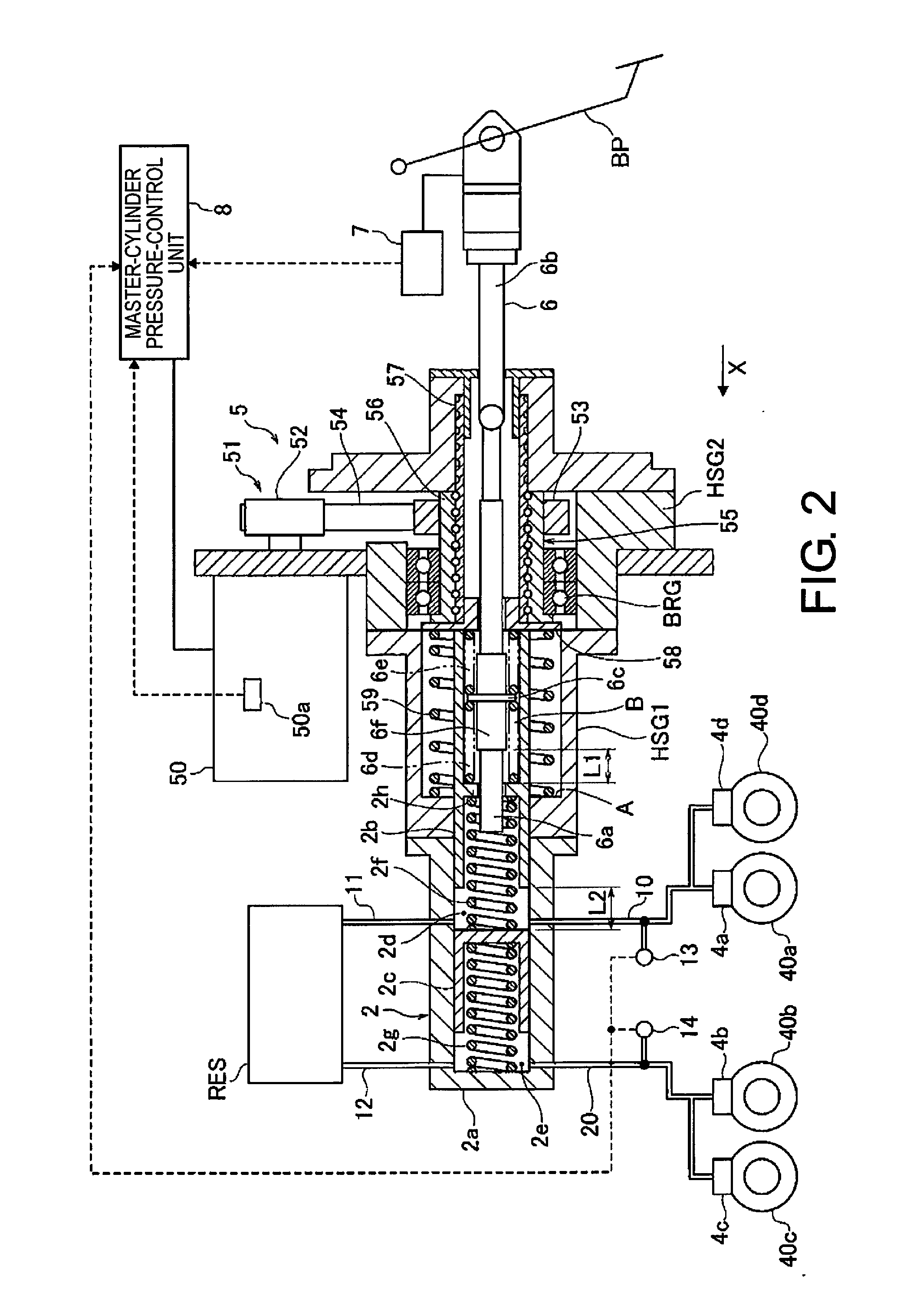
[0035]First, a configuration of the vehicle braking control device according to Embodiment 1 will now be described focusing on a basic configuration of an electric vehicle, a configuration of a braking device, a configuration of a control system, and a configuration for calculating a target displacement correction amount.

[0036]Basic Configuration of an Electric Vehicle

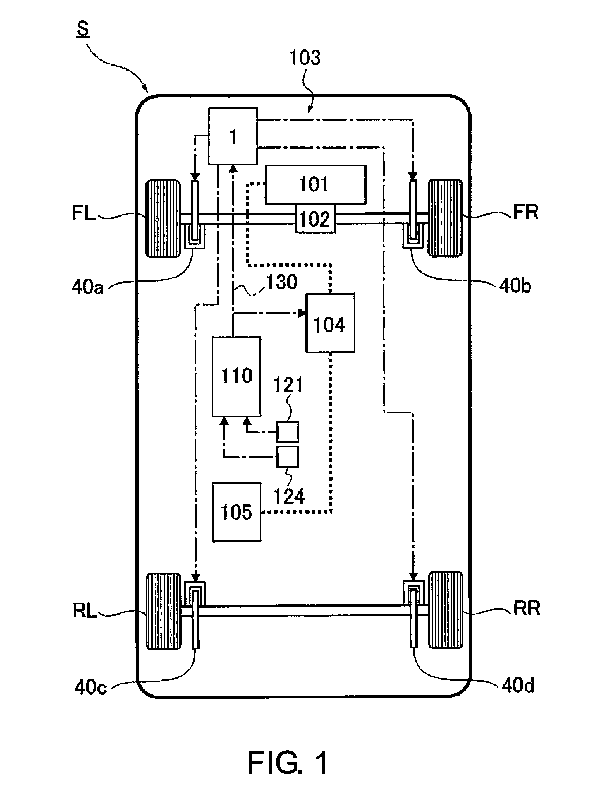
[0037]FIG. 1 is an overall view of an essential structure of an electric vehicle that has adopted the vehicle braking control device pursuant to Embodiment 1.

[0038]As shown in FIG. 1, an electric vehicle S pursuant to Embodiment 1 is equipped with a motor / generator 101; a reduction drive 102; a braking mechanism 103; left and right front wheels (drive wheels) FL, and FR; left and right rear wheels RL, and RR; and an integrated controller 110.

[0039]The motor / generator 101 is a synchronous type motor / generator with a permanent magnet embedded in a rotor, and a stator coil wrapped around a stator. This is interlocked to t...

embodiment 2

[0176]Embodiment 2 is an example where the target displacement-correction amount Δxδ is variable in response to a speed at which the driver operates the brake pedal.

[0177]FIG. 11 is a control block diagram of a target degree of relative displacement correction unit in the vehicle braking control device pursuant to Embodiment 2.

[0178]The vehicle braking control device pursuant to Embodiment 2 is equipped with a target relative displacement-amount correction unit 80A shown in FIG. 11. The target relative displacement-amount correction unit 80A is equipped with a brake consumed fluid amount estimating unit 81, a corrected displacement-amount calculating unit 82A, a target relative displacement-computing unit 83, and a brake-operation speed estimating unit 84.

[0179]The brake consumed fluid amount estimating unit 81 calculates the estimated amount of fluid consumed by braking Qα using the same procedures as those described in Embodiment 1. For that reason, a detailed description will be ...


PUM


Abstract

A vehicle braking control device includes a control unit that, when a characteristic representing the relationship between an estimated amount of fluid consumed by braking, which is estimated based on the amount a brake pedal is operated, and an actual master-cylinder pressure detected by a master-cylinder pressure detection unit is different from that of a preset characteristic in a reference map indicating representing the relationship between the amount of fluid consumed by braking and the master cylinder pressure, corrects a target value of a degree of relative displacement between an input member and an assist member by a target relative displacement-amount correction unit in a direction in which the difference between characteristics is reduced.

Description

CROSS-REFERENCE TO RELATED APPLICATIONS[0001]This application is a U.S. National stage application of International Application No. PCT / JP2013 / 055715, filed Mar. 1, 2013, which claims priority to Japanese Patent Application No. 2012-047798 filed in Japan on Mar. 5, 2012, the contents of each of which are hereby incorporated herein by reference.BACKGROUND[0002]1. Field of the Invention[0003]The present invention relates to a vehicle braking control device that generates force-multiplied brake hydraulic pressure in a master cylinder by an assist thrust imparted to an assist member in response to a movement of an input member.[0004]2. Background Information[0005]A conventional vehicle braking control device is known that uses an electric actuator to move an assist member in forward and backward directions, and multiplies the force to output a brake pedal input from a master cylinder (for example, see Patent JP 4784756 Publication). With this vehicle braking control device, controlling ...

Claims


Application Information

Patent Timeline
Patent Type & Authority Patents(United States)
IPC IPC(8): B60T13/00B60T13/66B60T7/04B60T13/02B60T13/74
CPCB60T13/66B60T7/042B60T13/662B60T13/745B60T13/02B60T13/74B60T2270/82
Inventor FUJIKI, NORIAKI
Owner NISSAN MOTOR CO LTD
Why Eureka
Try Eureka