Image display device

a display device and image technology, applied in the direction of printed circuit aspects, optics, instruments, etc., can solve the problems of high precision of connecting flexible printed circuits to liquid crystal panels and touch panels, difficult to make liquid crystal display devices thinner, display devices, etc., to prevent defective connections to flexible printed circuits. , the effect of high precision

Active Publication Date: 2012-04-26
JAPAN DISPLAY INC +1
View PDF4 Cites 43 Cited by
  • Summary
  • Abstract
  • Description
  • Claims
  • Application Information

AI Technical Summary

Benefits of technology

[0012]According to the present invention, one flexible printed circuit has wires connected to an image display panel and wires connected to a touch panel in such a manner that the flexible printed circuit is first connected to the image display panel and then connected to the touch panel. The flexible printed circuit is connected with high precision to the image display panel where the intervals between the wires is smaller, and then the flexible printed circuit is connected to the touch panel where the intervals between the wires is greater than in the image display panel, and thus the connections to the flexible printed circuit can be prevented fr

Problems solved by technology

Thus, the touch panel and the liquid crystal panel are provided in proximity, and therefore there are many wires in a small space which makes it difficult to make the liquid crystal display device thinner.
The same problem arises in organic EL display devices.
Therefore, the distance between the terminals for the liquid crystal panel on the flexible printed circuit and the terminals for the touch panel is short, whic

Method used


Image

  • Image display device
  • Image display device
  • Image display device

Examples


Embodiment Construction

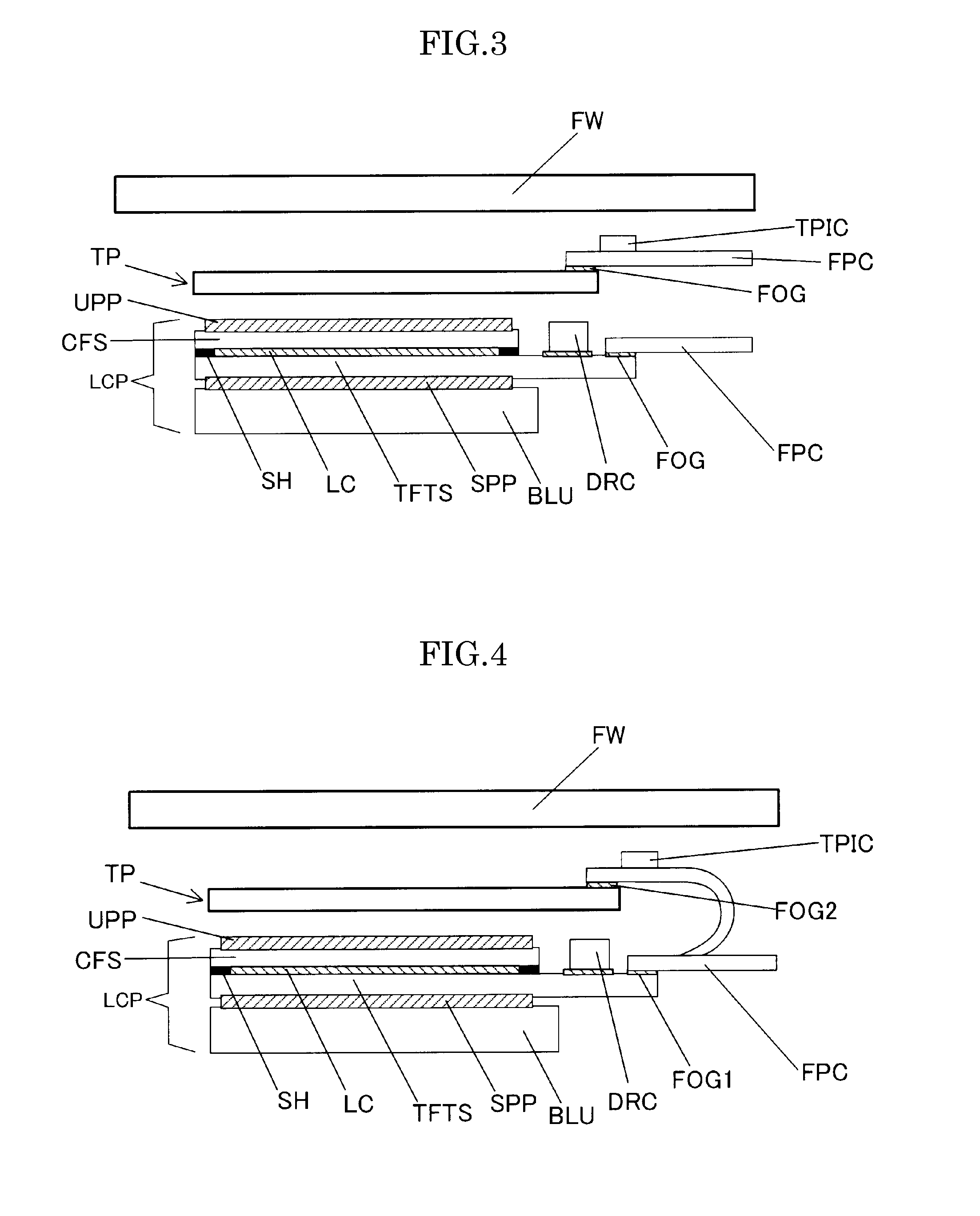
[0033]The image display device according to the present invention is described below in detail.

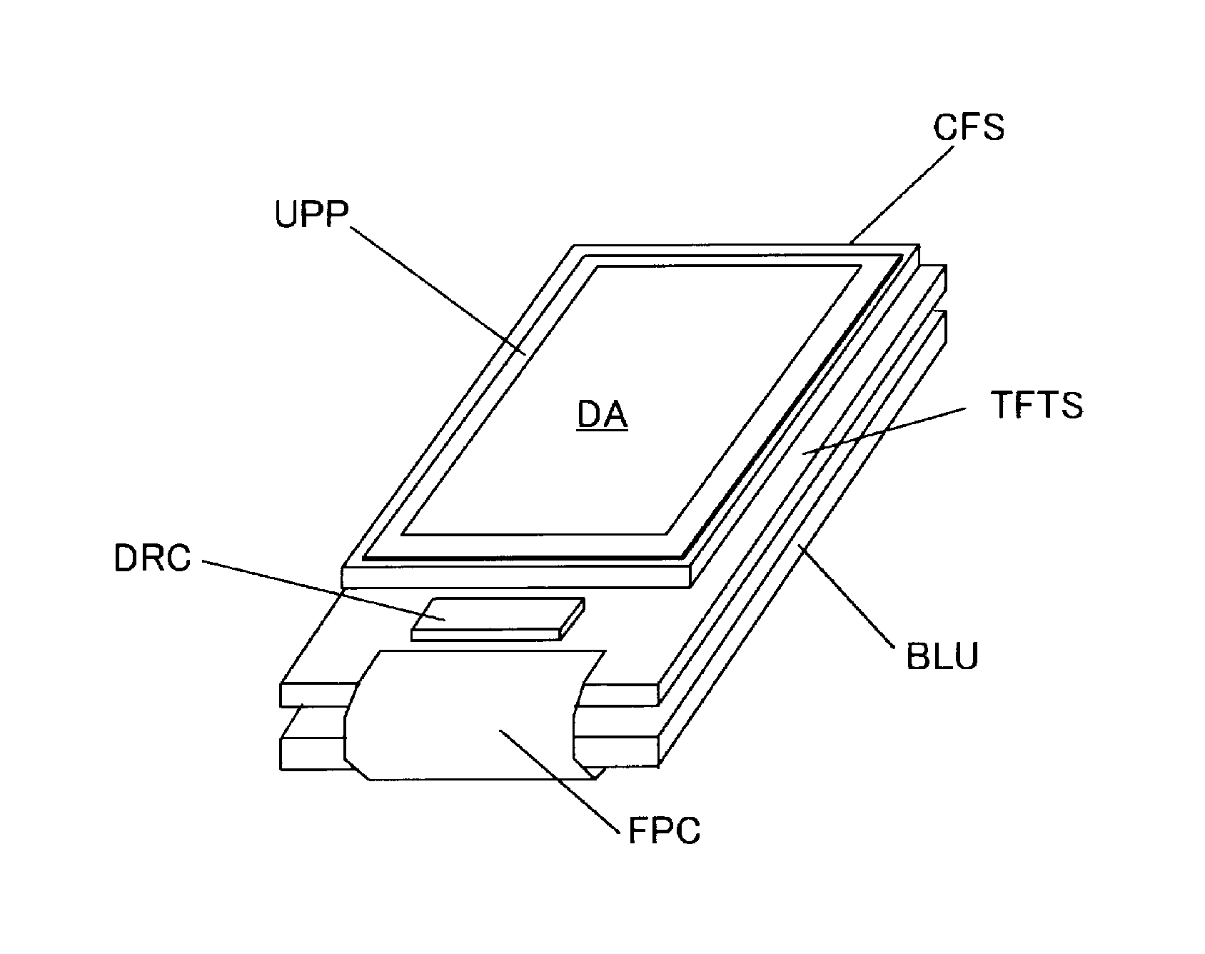
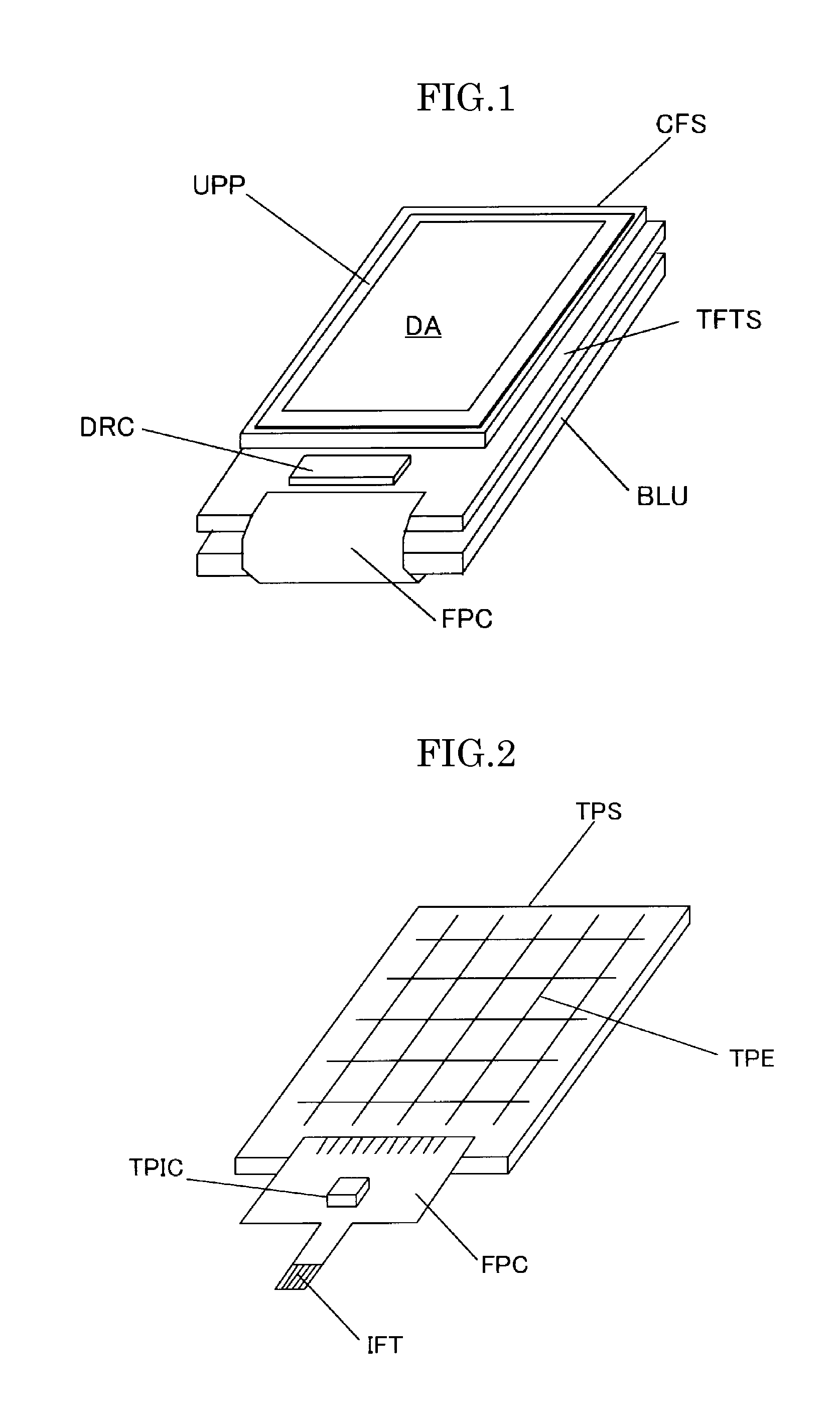
[0034]As shown in FIG. 4, the image display device according to the present invention is a liquid crystal display device having a liquid crystal panel LCP and a touch panel TP provided on the front surface of the liquid crystal panel is characterized in that wires connected to the liquid crystal panel and wires connected to the touch panel are included in one flexible printed circuit FPC, which is first connected (FOG1) to the liquid crystal panel (specifically, a TFT substrate (TFTS)) and then connected (FOG2) to the touch panel.

[0035]Here, the image display device according to the present embodiment is described using a liquid crystal display device as an example. However, the image display device is not limited to a liquid crystal display device and may be other image display devices, such as an organic electroluminescent display device. Therefore, the liquid crystal panel in the follow...


PUM


Abstract

A liquid crystal display device having a liquid crystal panel LCP and a touch panel TP provided on the front surface of the liquid crystal panel is characterized in that wires connected to the liquid crystal panel and wires connected to the touch panel are included in one flexible printed circuit FPC, which is first connected (FOG1) to the liquid crystal panel (specifically, a TFT substrate (TFTS)) and then connected (FOG2) to the touch panel.

Description

CROSS-REFERENCE TO RELATED APPLICATION[0001]The present application claims priority over Japanese Application JP 2010-239621 filed on Oct. 26, 2010, the contents of which are hereby incorporated into this application by reference.BACKGROUND OF THE INVENTION(1) Field of the Invention[0002]The present invention relates to an image display device, and in particular to an image display device having an image display panel, such as a liquid crystal panel or an organic electroluminescent panel, and a touch panel.(2) Description of the Related Art[0003]Thin image display devices, such as liquid crystal modules (liquid crystal display devices) and organic electroluminescent modules (organic EL display devices), are used for the display devices of many portable information apparatuses, such as cellular phones, personal data assistants (PDAs), digital cameras and multimedia players.[0004]FIG. 1 is a perspective diagram showing an example of a liquid crystal display device that is formed of a ...

Claims


Application Information

Patent Timeline
IPC IPC(8): G06F3/041
CPCG02F1/133308G02F1/13338G02F1/13452H05K2201/053H05K1/147H05K3/361H05K1/028
Inventor ABE, HIDEAKIKOBAYASHI, SETSUOABE, HIRONOBU
Owner JAPAN DISPLAY INC
Why Eureka
Try Eureka