Displacement drive, in particular window lifter drive

a technology of displacement drive and window lifter, which is applied in the direction of mechanical energy handling, supports/enclosures/casings, dynamo-electric machines, etc., can solve the problems of limiting the general accessible installation space or the extent of the adjustment drive, and achieves the reduction of the manufacturing time of the housing, the effect of significant cost savings and simple housing structur

Inactive Publication Date: 2012-06-07
ROBERT BOSCH GMBH
View PDF4 Cites 23 Cited by
  • Summary
  • Abstract
  • Description
  • Claims
  • Application Information

AI Technical Summary

Benefits of technology

[0003]The adjustment drive according to the invention now makes it possible, in particular by using the direct plug connection, to dispense with the drive-end plug pins or spring contacts. Dispensing with drive-end spring contacts leads to a completely new interface and contact-making concept which creates significant cost savings both in respect of die production and in respect of the individual parts and in respect of assembly. Furthermore, the resulting simpler housing structure with the spring contacts has various advantages in respect of the flexible design of the housing die as regards implementing a very wide variety of interface designs. As a further consequence of the advantageous direct plug connection, the die manufacturing time for the housing is reduced, as a result of which the entire development process for the adjustment drive is reduced and as a result of which customer-end changes, in particular to the interface, can be implemented very much more quickly. All these advantages are achieved by an adjustment drive according to the invention comprising an electric motor, an output shaft, a printed circuit board and a connection interface. In this case, the printed circuit board makes contact with the electric motor and the electric motor is designed to drive the output shaft. Furthermore, according to the invention, the connection interface comprises a direct plug connection with contact-making pads directly on the printed circuit board, with the contact-making pads being designed to make direct contact with spring contacts of a plug. According to the invention, the printed circuit board is arranged at an angle obliquely to a plane which lies perpendicular to the output shaft.
[0004]Particularly preferably, the angle of the printed circuit board is selected such that the contact-making pads are seated centrally in the connection interface. On account of this oblique arrangement of the printed circuit board, the contact-making pads can be positioned with a sufficient space from an upper and lower end of a housing of the adjustment drive. Particularly when the adjustment drive is provided as a window lifter in a vehicle door, it is necessary to limit the generally accessible installation space or the extent of the adjustment drive at least in the direction of the thickness of the door. In order to now make the position of the contact-making pads on the printed circuit board flexible and therefore to ensure there is a sufficient amount of freedom in terms of design for the customer-end or vehicle-end plug with the spring contacts, it is particularly advantageous to arrange the printed circuit board obliquely.
[0005]In a preferred embodiment, provision is made for the connection interface to be designed to receive a plug, wherein the contact-making pads are designed to make contact with spring contacts of the plug. A plug, which is connected to the connection interface at the customer- or vehicle-end, has projecting plug pins. These plug pins extend as far as the printed circuit board when the plug is connected to the connection interface, and therefore the spring contacts are connected to the contact-making pads directly on the printed circuit board. It is no longer necessary to solder or press projecting pins or spring contacts onto or into the printed circuit board of the adjustment drive.
[0009]In a further advantageous refinement, provision is made for the electric motor to comprise a brush support and a pole housing, wherein the brush support is inserted into the housing and the pole housing adjoins the brush support outside the housing. In particular, the pole housing is screwed to the housing and / or to the brush support. By virtue of this arrangement of the brush support in the housing, contact can be established between the printed circuit board and the brush support in a simple manner. To this end, the printed circuit board is advantageously located partially on or beneath the brush support.
[0010]In a further advantageous refinement of the electric motor used, the brush support has pins with press-in zones and / or solder zones for the purpose of making contact with the printed circuit board. This permits a flexible design of the connection between the printed circuit board and the electric motor or brush support.

Problems solved by technology

Particularly when the adjustment drive is provided as a window lifter in a vehicle door, it is necessary to limit the generally accessible installation space or the extent of the adjustment drive at least in the direction of the thickness of the door.

Method used


Image

  • Displacement drive, in particular window lifter drive
  • Displacement drive, in particular window lifter drive
  • Displacement drive, in particular window lifter drive

Examples


Embodiment Construction

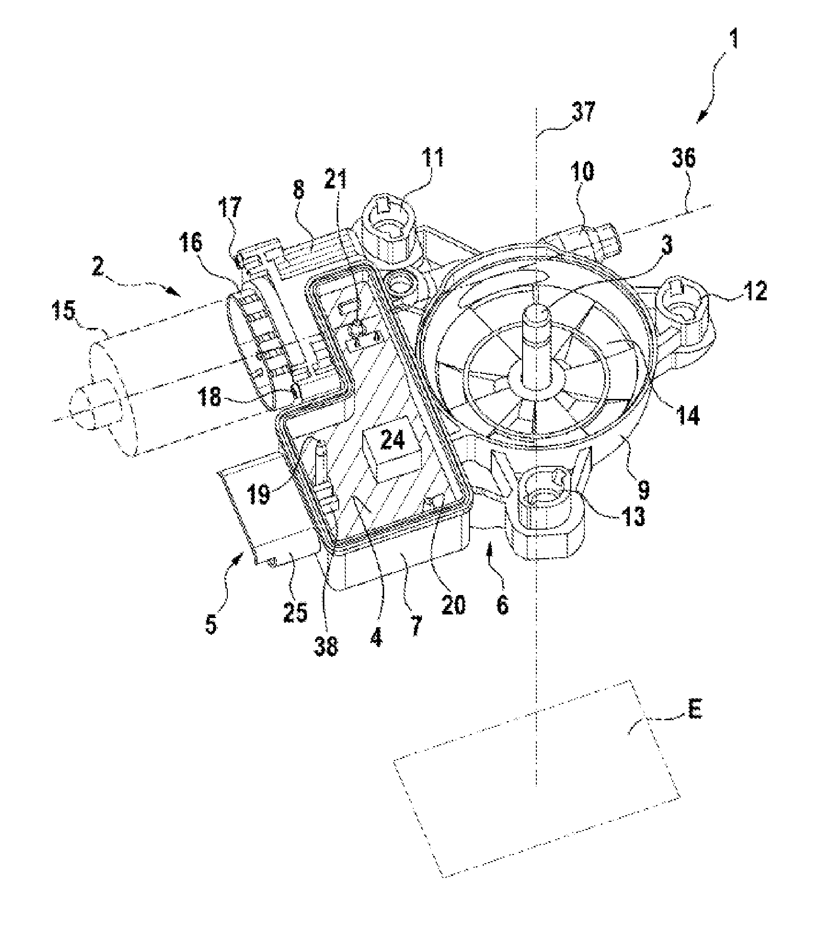
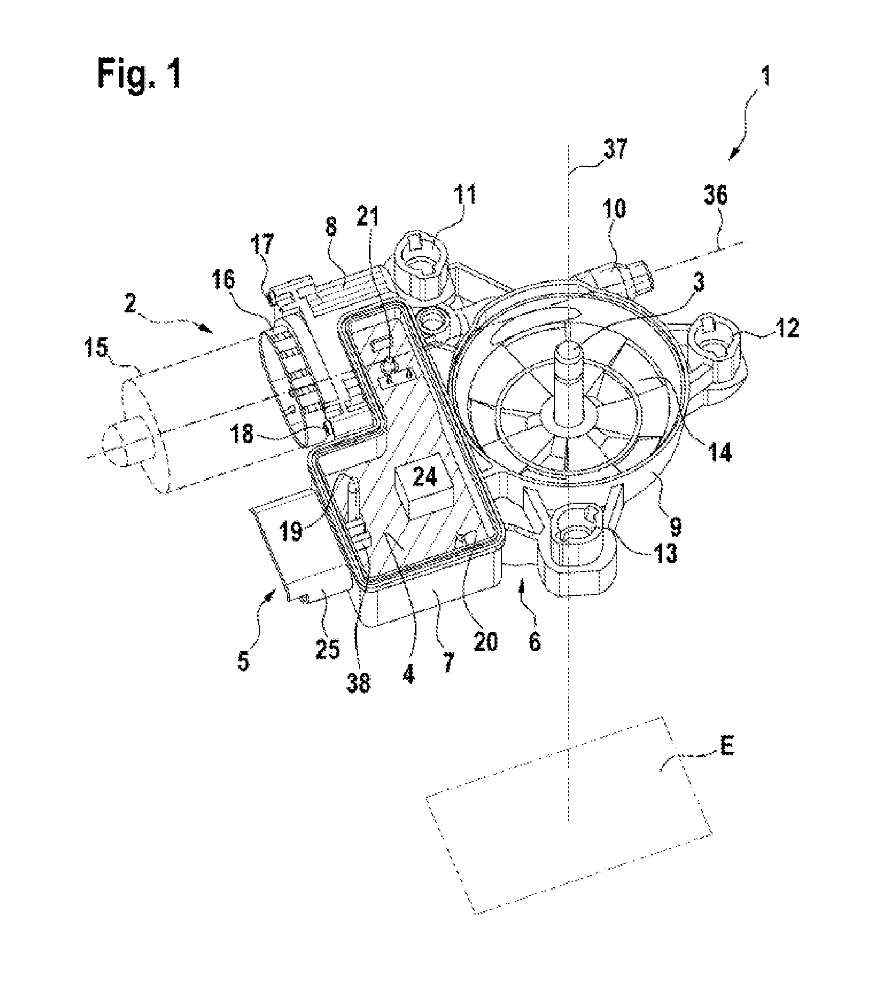
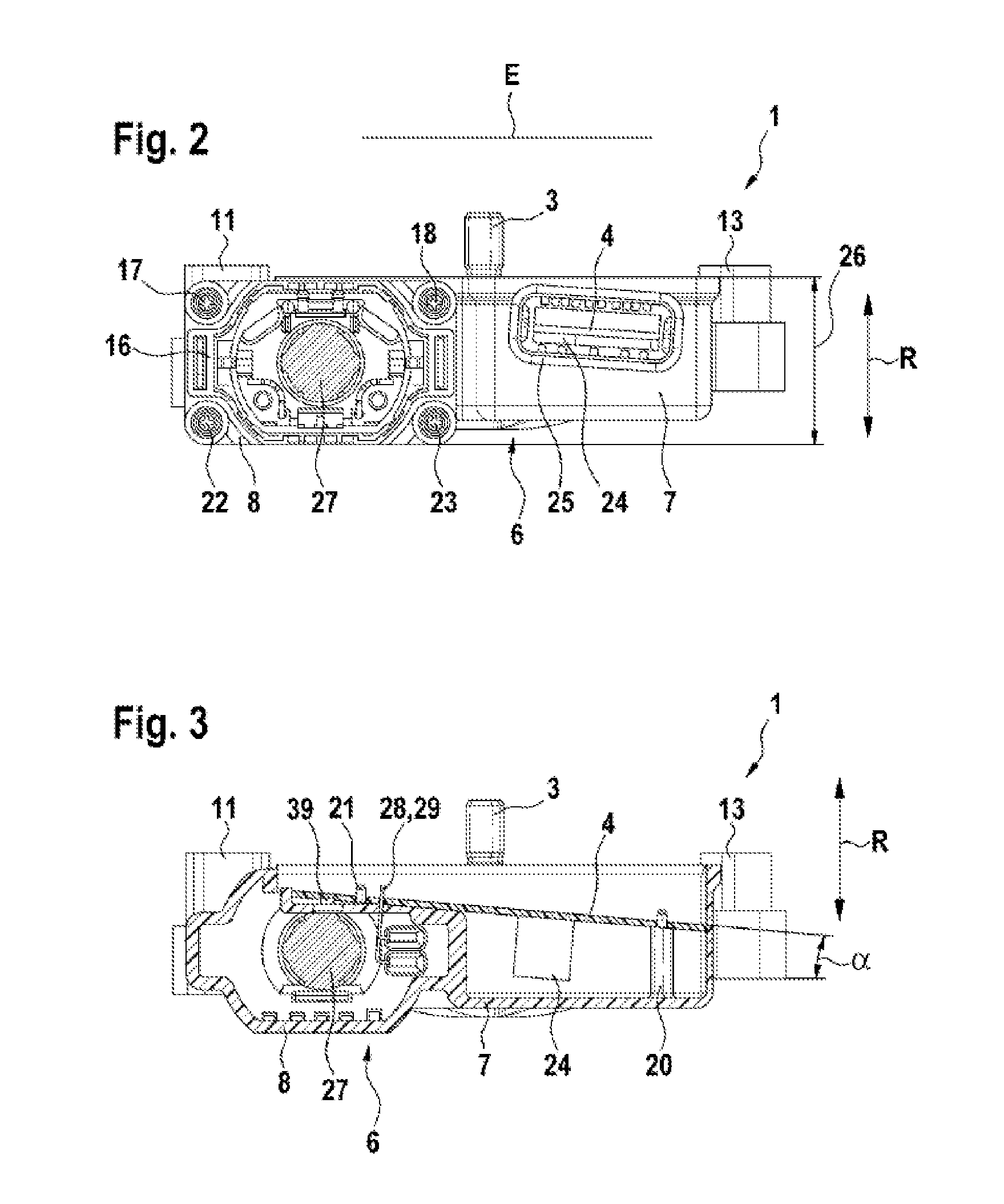
[0022]An exemplary embodiment of the adjustment drive 1, designed as a window lifter drive, will be described in greater detail below with reference to FIGS. 1 to 5.

[0023]In this case, FIG. 1 shows the adjustment drive 1, having an electric motor 2, an output shaft 3, a printed circuit board 4 and a connection interface 5. In this case, the electric motor 2 extends along an armature axis 36. The output shaft 3 extends along an output axis 37. The armature axis 36 and the output axis 37 do not intersect but are perpendicular to one another. A plane E is perpendicular to the output axis 37.

[0024]The adjustment drive 1 also comprises a housing 6. This housing 6 is divided into a printed circuit board housing portion 7, a motor housing portion 8 and a gear mechanism housing portion 9. In this case, the housing 6 is of integral design. A window lifter drive shaft mount 10 is formed in the housing 6 or in the gear mechanism housing portion 9. This window lifter drive shaft mount10 extends...


PUM


Abstract

The present invention relates to a displacement drive (1) comprising an electric motor (2), an output shaft (3), a printed circuit board (4) and a connection interface (5), the electric motor (2) making contact with the printed circuit board (4) and being designed to drive the output shaft (3), and the connection interface (5) comprising a direct plug connection with contact making pads (38) directly on the printed circuit board (4), and the contact making pads being designed to make direct contact with spring contacts of a plug.

Description

BACKGROUND OF THE INVENTION[0001]The present invention relates to an adjustment drive, in particular for use as a window lifter drive in a motor vehicle, comprising an electric motor, an output shaft, a printed circuit board and a connection interface.[0002]The prior art discloses window lifter drives with electronic printed circuit boards, with different functionalities, for example the trapping-prevention function, being realized in these drives. In order to connect the window lifter drives to customer-end, that is to say vehicle-end, interfaces, the housings of these drives have plug collars. Drive-end plug pins or spring contacts are formed in these plug collars. These plug pins are soldered into or pressed into the printed circuit board of the window lifter drive. The window lifter drive-end interface is therefore formed by projecting pins. In this case, the printed circuit boards are installed parallel or perpendicular to a screwing-on plane of the window lifter drive.SUMMARY ...

Claims


Application Information

Patent Timeline
Patent Type & Authority Applications(United States)
IPC IPC(8): H02K11/00
CPCH02K5/148H02K7/1166H02K11/0021H02K2213/06H02K11/0089H02K11/026H02K11/0073H02K11/215H02K5/225H02K2211/03H02K11/38
Inventor GOTTSCHALK, DANNY WERNERHUCK, THOMAS
Owner ROBERT BOSCH GMBH
Why Eureka
Try Eureka