Flow- optimized fluid line

a fluid line and flow optimization technology, applied in the field of fluid lines, can solve the problems of deterioration of the overall degree of effectiveness of the installation, increased production costs, and limited use possibilities, and achieve the effect of keeping the flow loss low

Inactive Publication Date: 2012-09-13
NORMA GERMANY GMBH
View PDF5 Cites 5 Cited by
  • Summary
  • Abstract
  • Description
  • Claims
  • Application Information

AI Technical Summary

Benefits of technology

[0007]Embodiments of the inventio...

Problems solved by technology

Due to friction and turbulences losses thereby occur, which can lead to a deterioration of an overall degree of effectiveness of an installation.
However, this is rel...

Method used


Image

  • Flow- optimized fluid line
  • Flow- optimized fluid line

Examples


Embodiment Construction

[0031]The particulars shown herein are by way of example and for purposes of illustrative discussion of the embodiments of the present invention only and are presented in the cause of providing what is believed to be the most useful and readily understood description of the principles and conceptual aspects of the present invention. In this regard, no attempt is made to show structural details of the present invention in more detail than is necessary for the fundamental understanding of the present invention, the description taken with the drawings making apparent to those skilled in the art how the several forms of the present invention may be embodied or formed in practice.

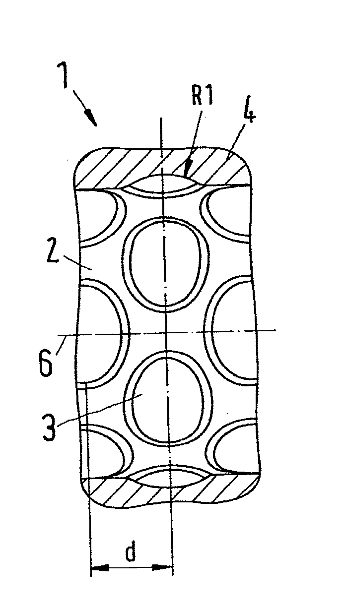
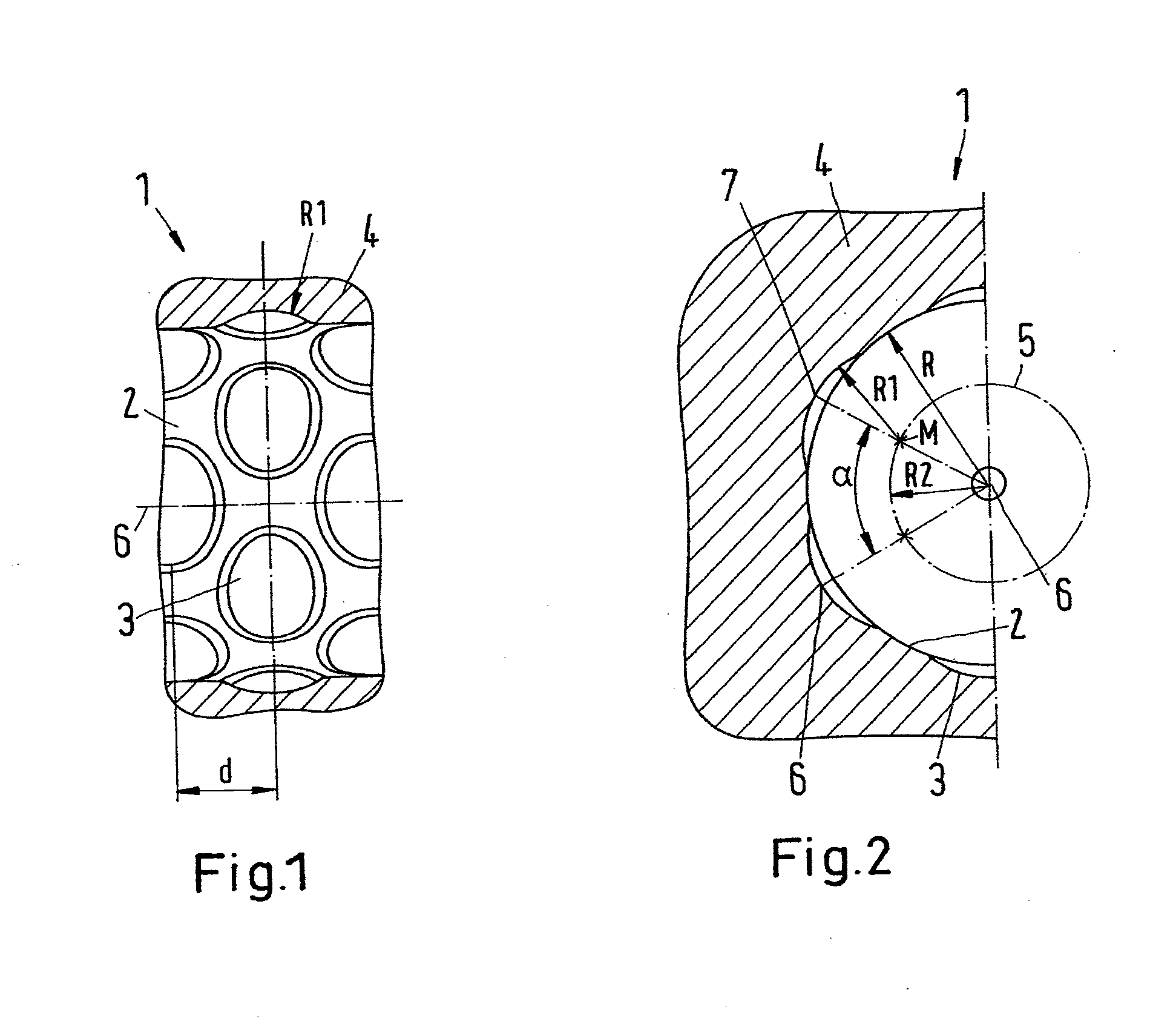
[0032]FIG. 1 shows a partial section of a fluid line 1, wherein the fluid line 1 is shown in longitudinal section so that an inner surface 2 of fluid line 1 can be seen. Recesses 3 are shaped and uniformly distributed in inner surface 2. Inner surface 2 is otherwise provided with a smooth surface.

[0033]Recesses ...


PUM

PropertyMeasurementUnit
Fractionaaaaaaaaaa
Fractionaaaaaaaaaa
Fractionaaaaaaaaaa

Abstract

Fluid line and method of forming the fluid line. The fluid line includes a cylindrical inner surface having uniformly distributed recesses in the form of spherical sectors formed in the inner surface.

Description

CROSS-REFERENCE TO RELATED APPLICATIONS [0001]The present application claims priority under 35 U.S.C. §119(a) of German Patent Application No. 10 2011 013 572.3, filed on Mar. 10, 2011, the disclosure of which is expressly incorporated by reference herein in its entiretyBACKGROUND OF THE INVENTION [0002]1. Field of the Invention[0003]Embodiments of the invention relate to a fluid line with a cylindrical inner surface.[0004]2. Discussion of Background Information[0005]Fluid lines are used in many fields of application for conveying fluids, in particular liquids. Due to friction and turbulences losses thereby occur, which can lead to a deterioration of an overall degree of effectiveness of an installation. In particular in the case of smooth pipes, and in the smooth regions of partially corrugated pipes, the really usable flow cross section is often much smaller than the free inner cross section in the fluid line, since a quasi-stationary boundary layer forms in the edge region.[0006]...

Claims


Application Information

Patent Timeline
IPC IPC(8): F16L9/00B29C47/00B29C69/02B23P17/00
CPCF16L9/006F16L9/127Y10T29/49F15D1/005F15D1/065F16L9/06F16L55/00
Inventor BAUER, ANDREAS
Owner NORMA GERMANY GMBH
Why Eureka
Try Eureka