This helps you quickly interpret patents by identifying the three key elements:
Problems solved by technology
Method used
Benefits of technology
[0019]According to one or more exemplary embodiments of the present disclosure, it is possible to realize an ultrasound diagnostic appar
Problems solved by technology
With the conventional method, however, in the case where the measurement reference images are inappropriate, that is, the case in which the respective measurement refer
Method used
Image
Click on the blue label to locate the original text in one second.
Reading with bidirectional positioning of images and text.
Examples
embodiment 1
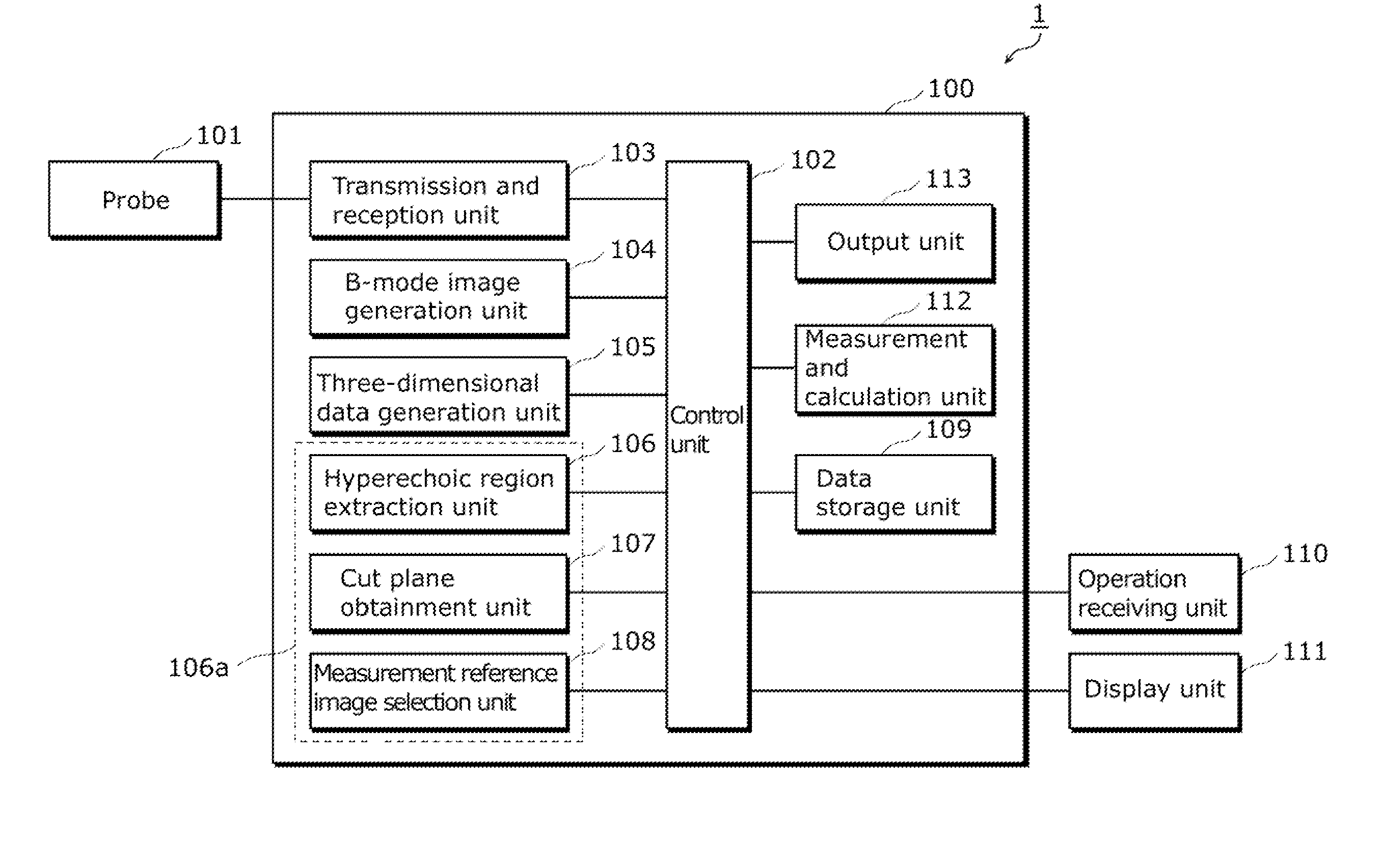
[0040]FIG. 1 is a block diagram showing an outline of an ultrasound diagnostic apparatus according to Embodiment 1 of the present disclosure.
[0041]An ultrasound diagnostic apparatus 1 shown in FIG. 1 is configured of an ultrasound diagnostic apparatus main body 100, a probe 101, an operation receiving unit 110, and a display unit 111.
[0042]The ultrasound diagnostic apparatus main body 100 includes a control unit 102, a transmission and reception unit 103, a B-mode image generation unit 104, a three-dimensional data generation unit 105, a measurement image selection unit 106a which includes a hyperechoic region extraction unit 106, a cut plane obtainment unit 107, and a measurement reference image selection unit 108, a data storage unit 109, a measurement and calculation unit 112, and an output unit 113.
[0043]The probe 101 is connected to the ultrasound diagnostic apparatus main body 100, and ultrasound transducers for transmitting and receiving ultrasound waves are arranged in the p...
embodiment 2
[0110]FIG. 13 is a block diagram showing an outline of the ultrasound diagnostic apparatus according to Embodiment 2 of the present disclosure. In FIG. 13, constituent elements that are the same as those in FIG. 1 use the same reference numerals, and the description thereof shall not be repeated.
[0111]The ultrasound diagnostic apparatus 2 shown in FIG. 13 is configured of an ultrasound diagnostic apparatus main body 200, the probe 101, the operation receiving unit 110, and the display unit 111. The configuration of a subject's body region specification unit 212 is what makes the ultrasound diagnostic apparatus main body 200 shown in FIG. 13 different from the ultrasound diagnostic apparatus main body 100 shown in FIG. 1. Namely, the ultrasound diagnostic apparatus main body 200 has the subject's body region specification unit 212 in addition to the configuration shown in FIG. 1.
[0112]The subject's body region specification unit 212 specifies a region, in the body of the subject, whi...
PUM
Abstract
An ultrasound diagnostic apparatus according to the exemplary embodiments of the present disclosure includes: a three-dimensional data generation unit which generates three-dimensional data for each region in the body of a subject based on reflected waves reflecting back from the body of the subject after ultrasound waves have been transmitted towards the body of the subject; a measurement image selection unit which respectively selects, for each region, one of the two-dimensional cross-sections that compose the three-dimensional data, as a measurement reference image used for measuring a length of each region in the body of the subject; a measurement calculation unit which measures a length of each region in the body of the subject using the respectively selected measurement reference image, and calculates an estimated weight of the subject using the measured lengths; and a display unit which outputs the estimated weight thus calculated.
Description
CROSS REFERENCE TO RELATED APPLICATIONS [0001]This is a continuation application of PCT Patent Application No. PCT / JP2011 / 005365 filed on Sep. 26, 2011, designating the United States of America, which is based on and claims priority of Japanese Patent Application No. 2010-222568 filed on Sep. 30, 2010. The entire disclosures of the above-identified applications, including the specifications, drawings and claims are incorporated herein by reference in their entirety.TECHNICAL FIELD [0002]Apparatuses consistent with one or more exemplary embodiments of the present disclosure relate to ultrasound diagnostic apparatuses, and particularly relate to an ultrasound diagnostic apparatus used for examination on the growth of a fetus.BACKGROUND ART [0003]Ultrasound-based diagnostic imaging, by its nature of utilizing sound waves, affects less the human body. Therefore, the ultrasound-based diagnostic imaging is often used for prenatal checkups, and the condition in which a fetus grows is exami...
Claims
Application Information
Patent Timeline
Application Date:The date an application was filed.
Publication Date:The date a patent or application was officially published.
First Publication Date:The earliest publication date of a patent with the same application number.
Issue Date:Publication date of the patent grant document.
PCT Entry Date:The Entry date of PCT National Phase.
Estimated Expiry Date:The statutory expiry date of a patent right according to the Patent Law, and it is the longest term of protection that the patent right can achieve without the termination of the patent right due to other reasons(Term extension factor has been taken into account ).
Invalid Date:Actual expiry date is based on effective date or publication date of legal transaction data of invalid patent.