Three-Dimensional Stereoscopic Display Apparatus

a display apparatus and three-dimensional technology, applied in the field of display apparatuses, can solve the problems of low quality of display apparatuses and decrease of total luminance, and achieve the effects of reducing spatial crosstalk, and increasing the viewing angle of display apparatuses

Inactive Publication Date: 2012-09-27
SAMSUNG DISPLAY CO LTD
View PDF10 Cites 9 Cited by
  • Summary
  • Abstract
  • Description
  • Claims
  • Application Information

AI Technical Summary

Benefits of technology

[0031]According to exemplary embodiments of the present invention, the backlight assembly emits light substantially straight, so that crossover of the left eye image into the observer's right eye and crossover of the right eye image into the observer's left eye is minimized and a spatial crosstalk is reduced. Moreover, the diffusing filter is disposed on the phase delaying plate to generally diffuse the straight light, so that the viewing angle of the display apparatus may be increased.
[0032]Moreover, the viewing angle of the display apparatus may be increased without the use of a light shielding layer, such as a black matrix, on the phase delaying plate, and thus total luminance may be prevented from being decreased.

Problems solved by technology

However, since the optical plate is attached on the display panel to display the 3D image, crosstalk, in which the left eye image may not be filly blocked from the right eye and the right eye image may not be fully blocked by the left eye, may occur according to the viewing angle of the observer.
Thus, the display apparatus may have low quality when viewed outside of a preferred viewing angle.
However, the light shielding layer decreases amount of light emitted from the optical plate, so that total luminance decreases.

Method used


Image

  • Three-Dimensional Stereoscopic Display Apparatus
  • Three-Dimensional Stereoscopic Display Apparatus
  • Three-Dimensional Stereoscopic Display Apparatus

Examples


Embodiment Construction

[0041]Hereinafter, exemplary embodiments of the present invention will be explained in detail with reference to the accompanying drawings.

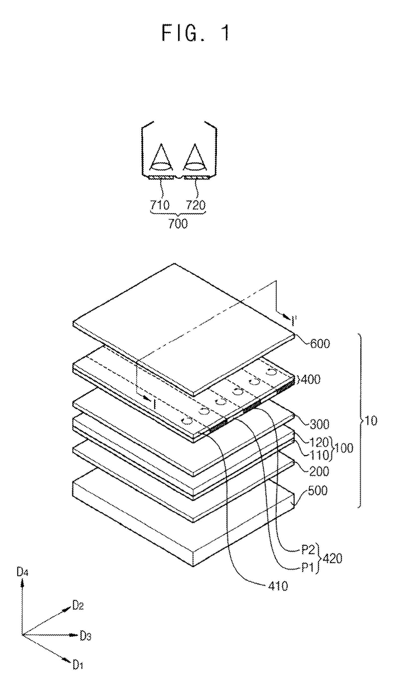
[0042]FIG. 1 is a conceptual perspective view illustrating a display apparatus according to an exemplary embodiment of the present invention.

[0043]Referring to FIG. 1, the display apparatus 10 includes a display panel 100, a first polarizing plate 200, a second polarizing plate 300, a phase delaying plate 400, a backlight assembly 500 and a diffusing filter 600.

[0044]The display panel 100 displays an image using light provided from the backlight assembly 500. For example, the display panel 100 may be a liquid crystal display panel including a first substrate 110, a second substrate 120 facing the first substrate 110, and a liquid crystal layer (not shown) disposed therebetween. The display panel 100 may be disposed over the backlight assembly 500.

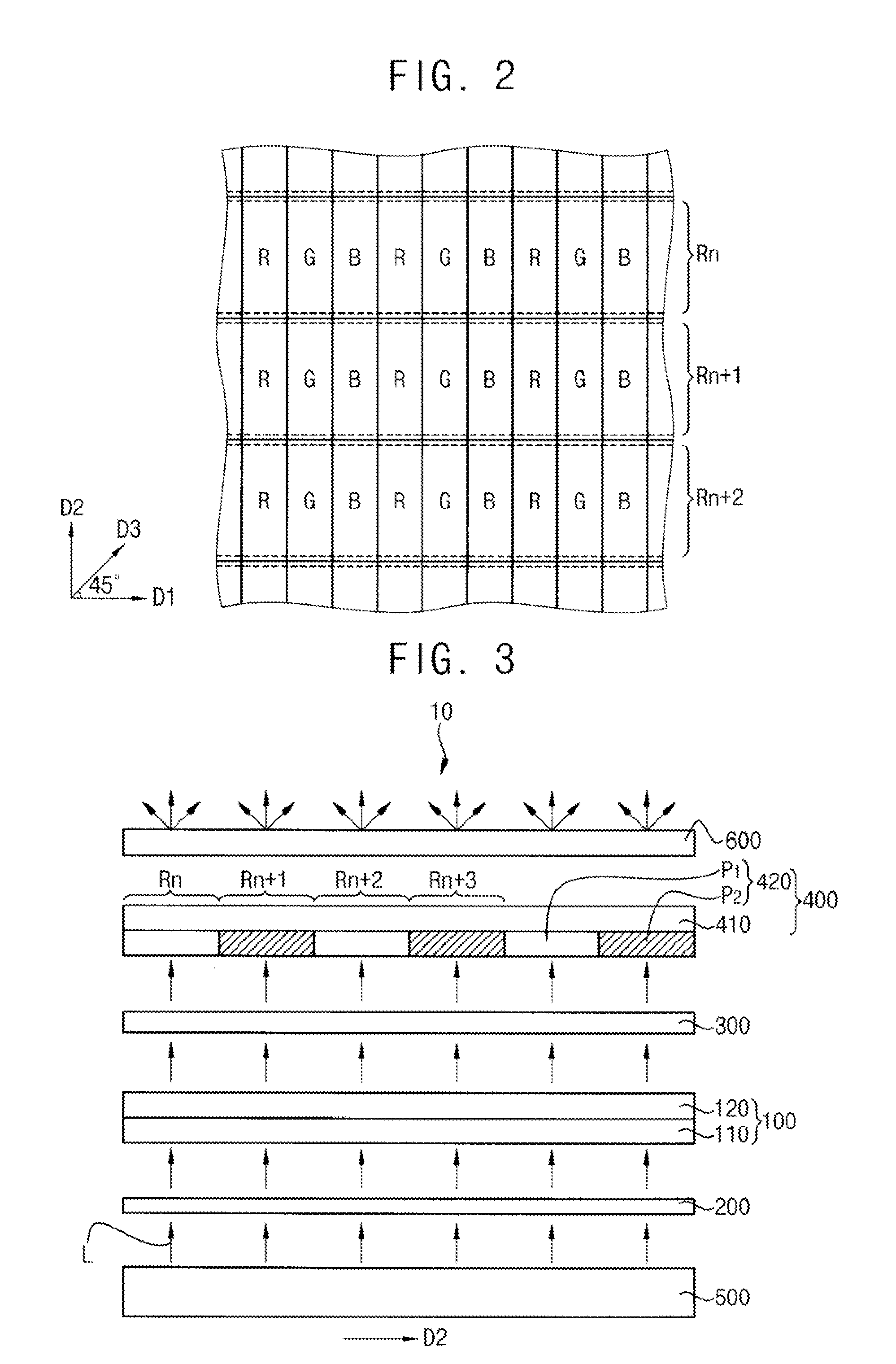
[0045]The first polarizing plate 200 is disposed between the display panel 100 and the backlight assem...


PUM

PropertyMeasurementUnit
phaseaaaaaaaaaa
phase delayingaaaaaaaaaa
average wavelengthaaaaaaaaaa

Abstract

A display apparatus includes a display panel displaying an image. A backlight assembly is disposed under the display panel. A phase delaying plate is disposed on the display panel. The backlight assembly emits a collimated light in a direction substantially perpendicular to the display panel. The phase delaying plate includes a phase delaying layer. The phase delaying layer includes a first pattern delaying a phase of the light passing the display panel by a first phase and a second pattern delaying the phase of the light passing the display panel by a second phase. The second phase is different from the first phase. Accordingly, a spatial crosstalk may be minimized and the optimal viewing angle of the display apparatus may be increased.

Description

PRIORITY STATEMENT[0001]This application claims priority under 35 U.S.C. §119 to Korean Patent Application No. 10-2011-0026963, filed on Mar. 25, 2011, in the Korean Intellectual Property Office (KIPO), the contents of which are herein incorporated by reference in their entireties.BACKGROUND[0002]1. Technical Field[0003]The present invention relates to a display apparatus. More specifically, the present invention relates to a display apparatus displaying a 3-dimensional stereoscopic image.[0004]2. Discussion of the Related Art[0005]A liquid crystal display (LCD) apparatus is a form of flat-panel display device that utilized liquid crystal to display an image by changing the transmissivity of light though individual display pixels. Because the liquid crystal display does not generate its own light, it receives light from a backlight assembly. The LCD is capable of displaying a 2-dimensional image (hereinafter, referred to as a 2D image). LCDs have been devised for displaying a 3-dime...

Claims


Application Information

Patent Timeline
Patent Type & Authority Applications(United States)
IPC IPC(8): G02F1/1335
CPCG02F1/133504G02F1/13363G02B27/26G02F2001/133638G02F2001/133562G02F2001/133631G02F2001/133541G02B30/25G02F1/133541G02F1/133562G02F1/133631G02F1/133638G02F1/133524G02F1/133528G02F1/133602
Inventor JUNG, JAE-WOOKIM, AH-REUMHUR, SE-HUHNSON, HO-SEOK
Owner SAMSUNG DISPLAY CO LTD
Why Eureka
Try Eureka