
Reverse electrodialysis supported microbial fuel cells and microbial electrolysis cells
a technology of microbial fuel cells and reverse electrodialysis, which is applied in the direction of electrodialysis, refrigeration components, energy input, etc., can solve the problems of limited electrical linking of mfc reactors in series, no method or device is believed to have been developed prior to the invention of the first generation
Patent Information
- Authority / Receiving Office
- US · United States
- Current Assignee / Owner
- Publication Date
- 2012-11-22
Smart Images
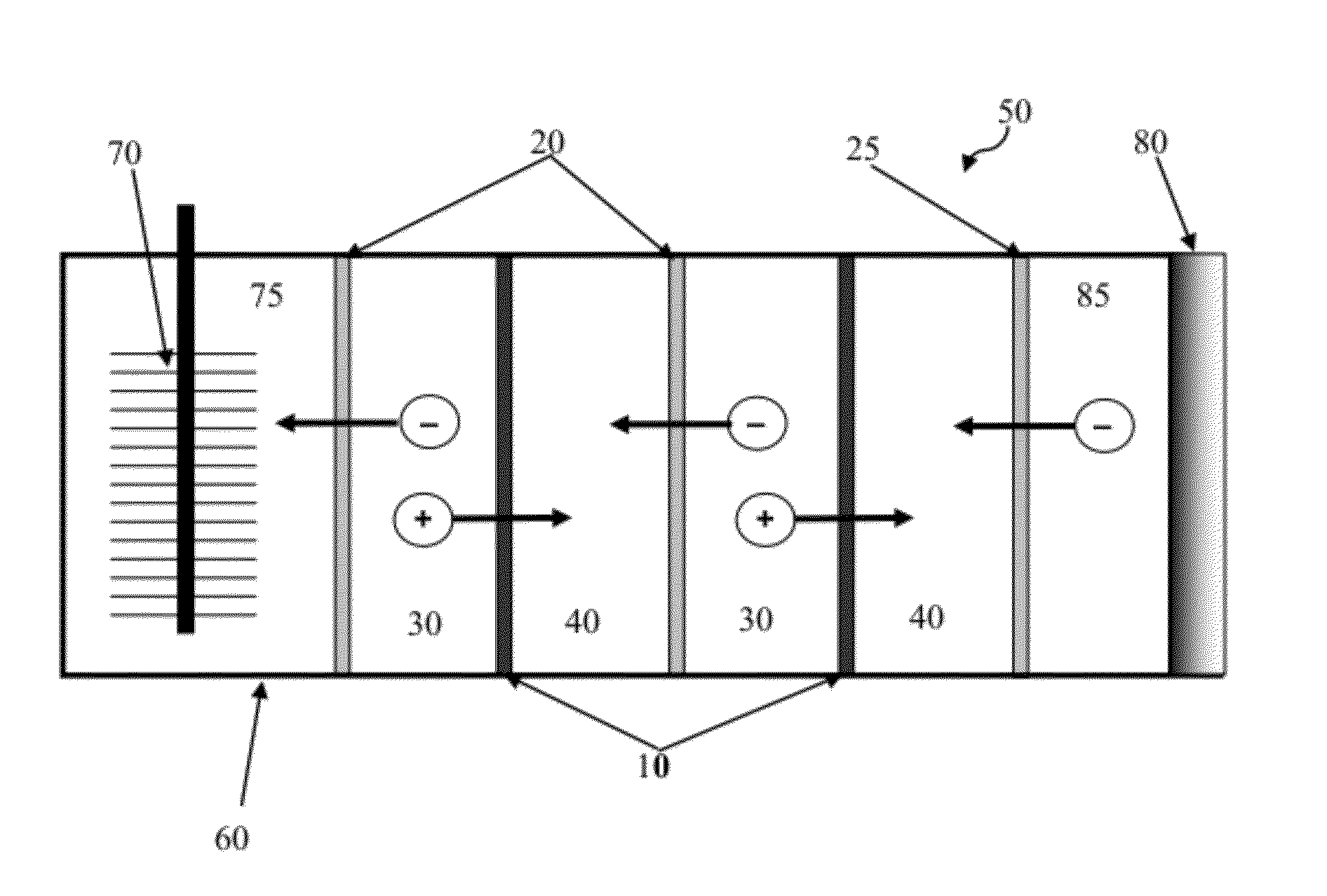
Figure 1 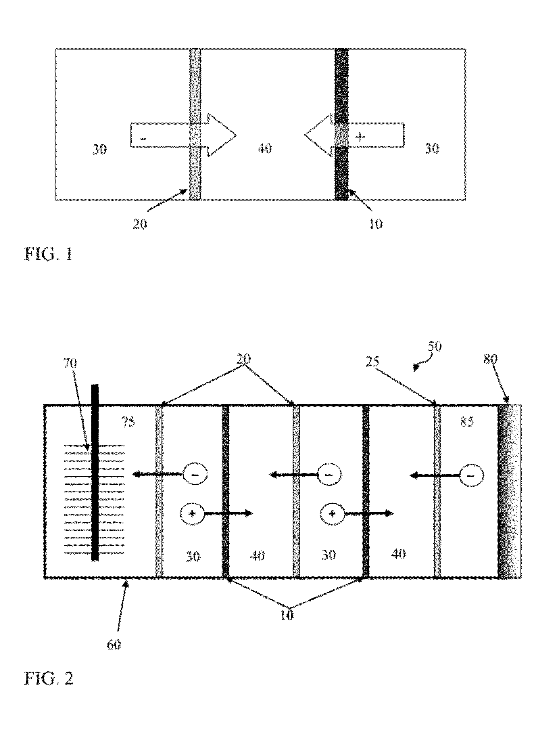
Figure 2 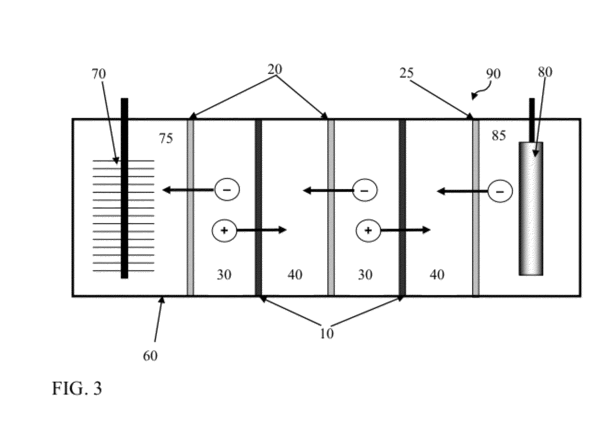
Figure 3
Abstract
Description
REFERENCE TO RELATED APPLICATIONS
[0001] This application claims priority from U.S. Provisional Patent Application Ser. Nos. 61 / 487,107, filed May 17, 2011; 61 / 544,067, filed Oct. 6, 2011; and 61 / 598,635, filed Feb. 14, 2012. The entire content of each application is incorporated herein by reference.FIELD OF THE INVENTION
[0002] Microbial systems incorporating reverse electrodialysis for generation of products such as power or hydrogen are provided according to embodiments of the present invention.BACKGROUND OF THE INVENTION
[0003] A microbial fuel cell (MFCs) is a type of bioelectrochemical system (BES) where current is generated by bacteria from the oxidation of organic and inorganic matter. Compounds are reduced at the cathode, such as oxygen or protons, through inorganic catalysts or bacteria and electrical power is generated in an MFC.
[0004] Ordinary fuel cells (i.e. PEM hydrogen fuel cells) can be linked in series to increase voltage, but when MFCs are electrically linked in series t...
Examples
example 1
[0249]MRC Construction
[0250]For the outer chambers of the MRC, two blocks of Lexan were drilled to make a cylindrical cathode (18 mL) and anode (30 mL) chambers with a cross-sectional area of 7 cm2. The air cathode was prepared with a platinum catalyst on the water side (3.5 mg Pt over 7 cm2) with a Nafion binder, and four polytetrafluoroethylene diffusion layers were coated on the air side. The anode, a graphite fiber brush 2.7 cm in diameter and 2.3 cm long (Mill-Rose Lab Inc., OH), was inoculated with effluent from an existing MFC and enriched by operation in a conventional single chamber MFC. During this start-up stage, NaCl concentration was gradually raised so that the microbial activity would not be affected by salinity during the following MRC operation.
[0251]The RED stack in this example included 10 cells (called subunits herein) in total, with 5 seawater cells (saline material compartments) and 5 river water cells (lower-saline material compartments) alternately sandwiched...
example 2
[0284]MREC Construction
[0285]A cubic Lexan block with a cylindrical chamber (˜30 mL; 7 cm2 in cross section) was used for an anode and cathode container, with a glass tube (20 mL) glued to the top of the cathode chamber to collect H2. The stainless steel mesh (SS) cathode was prepared with platinum (0.6 mg / cm2; BASF, Germany) as the catalyst (except as indicated) in a mixture of carbon black and Nafion on both sides of a 7-cm2 stainless steel mesh (#50). In some tests the SS cathode was prepared with MoS2 (6.3 mg / cm2) as a replacement of the Pt catalyst. The carbon cloth (CC) cathode was made with a Pt catalyst (0.5 mg / cm2) in the same manner using a 7-cm2 piece of carbon cloth. The anode (a graphite fiber brush 2.7 cm in diameter and 2.3 cm in length; Mill-Rose Lab Inc., OH) was inoculated with the effluent from an existing MFC and initially enriched in a single chamber MFC. During this start-up stage, the anode microbes were acclimated to a gradually increase in NaCl concentration...
example 3
[0331]FIG. 7 illustrates a process of the current invention where effluent circulated through the RED stack is regenerated in a distillation column into a saline material (regenerated concentrate solution) and a lower-saline material (regenerated dilute solution). Here the anode and cathode solutions are shown as once-through, but they can be recycled.
[0332]FIG. 15 illustrates model results by using Eq. (1). The model results obtained using Eq. 1, and shown in FIG. 15, indicate that the NH4HCO3 concentration in the concentrate solution (saline material) should be greater than ˜0.5 molal, but a concentration greater than 1 molal does not significantly improve the cell potential. For the model simulation, the transport numbers were: tcounter=0.9 and tco=0.1. The activity coefficients were determined by Pitzer equation with parameters of KHCO3 by (Pitzer and Pelper, 1980).