Water inlet device for a water tank

Inactive Publication Date: 2013-03-28
HUANG SO MEI
View PDF13 Cites 5 Cited by
  • Summary
  • Abstract
  • Description
  • Claims
  • Application Information

AI Technical Summary

Benefits of technology

The water inlet device improves the efficiency of the water tank by reducing the noise and vibration caused by the inflowing current. This results in a quieter life for the user.

Problems solved by technology

1. Since the conventional structure lacks current buffer design, the momentum is very strong and often produces water rushing noise during inflowing to disturb quiet life.
2. Due to lack of the anti-shake design of the rubber ring pad between each component of the conventional structure, for example, since the anti-shake rubber ring pads between the water supply pipe 12 and the internal water-lifting pipe 13 are not enough, shaking often occur during current flows in and out, the condition may strengthen the formation of the noise and be criticized by users.

Method used


Image

  • Water inlet device for a water tank
  • Water inlet device for a water tank
  • Water inlet device for a water tank

Examples


Embodiment Construction

[0034]The above and further objects and novel features of the invention will more fully appear from the following detailed description when the same is read in connection with the accompanying drawing. It is to be expressly understood, however, that the drawing is for purpose of illustration only and is not intended as a definition of the limits of the invention.

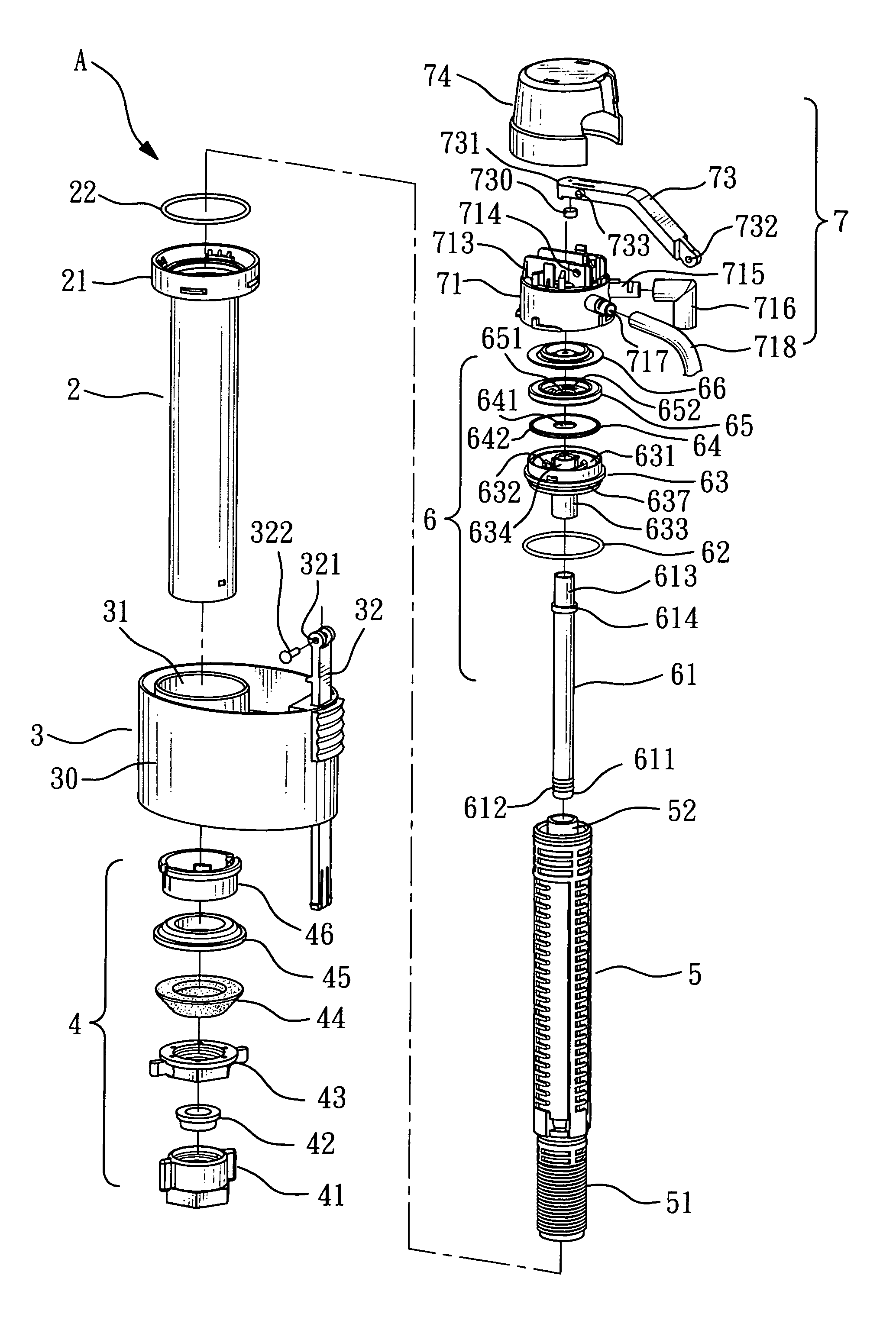
[0035]Please refer to FIG. 3, FIG. 4 and FIG. 6, according to the water inlet device A of the water tank of the present invention, a float seat 3 is slipped outside an external water-lifting pipe 2, and an internal water-lifting pipe 5 is set inside the external water-lifting pipe 2. An external threaded section 51 set on the lower section of the internal water-lifting pipe 5 is used to fasten a fixed set 4 to fix on a water inlet of the water tank (Since this part is a conventional structure, it is not illustrated in figures). A control valve 7 is fixedly connected on the upper end of the external water-lifting pipe 2, and ...


PUM


Abstract

The invention relates to the structure of a water inlet device of a water tank, wherein a float seat is slipped outside an external water-lifting pipe, an internal water-lifting pipe is installed inside the external water lifting pipe, a control valve is fixedly connected on the upper end of the external water-lifting pipe, a valve set is set inside the control valve, the valve set includes a membrane, a positioning plate, a silencing washer, a water feeding plate and a water supply pipe. The shock and vibration caused by inflowing water current may be buffered by using the construction of the valve set, to thereby enhance the silence effect and achieve the purpose of reducing noise.

Description

BACKGROUND OF THE INVENTION[0001]1. Field of the Invention[0002]The invention relates to the structure of a water inlet device and, more particularly, to the structure of the water inlet device capable to enhance the silence effect, to thereby reduce the produced noise and ensure silence in life.[0003]2. Brief Description of the Related Art[0004]As shown in FIG. 1 and FIG. 2, it is the structure of a conventional water inlet device 1 for a water tank (the structure in U.S. Pat. No. 5,836,346), where an internal water-lifting pipe 13 installed inside an external water-lifting pipe 11, and a water supply pipe 12 is slipped inside the internal water-lifting pipe 13. A valve seat 14 is combined on the upper end of the external water-lifting pipe 11 and the water supply pipe 12, a cap 15 is covered outside the valve seat 14. An infundibuliform plate 121 is set on the upper end of the water supply pipe 12, and a membrane 16 and a controlling seat 143 are installed on it. By changing the p...

Claims


Application Information

Patent Timeline
IPC IPC(8): F16K31/18
CPCF16K31/34E03D1/32Y10T137/7358
Inventor HUANG, SO-MEI
Owner HUANG SO MEI
Why Eureka
Try Eureka