Roller press having torque balance

Inactive Publication Date: 2013-04-11
KHD HUMBOLDT WEDAG GMBH
View PDF7 Cites 9 Cited by
  • Summary
  • Abstract
  • Description
  • Claims
  • Application Information

AI Technical Summary

Benefits of technology

[0006]The object of the invention is therefore to refine the roller presses such that the centering is designed such that it can be produced more

Problems solved by technology

In roller presses having rolls with a weight of up to 50 metric tons, an appropriately large dimensioning of the machine frame is necessary, so that, in a necessary

Method used


Image

  • Roller press having torque balance
  • Roller press having torque balance
  • Roller press having torque balance

Examples


Embodiment Construction

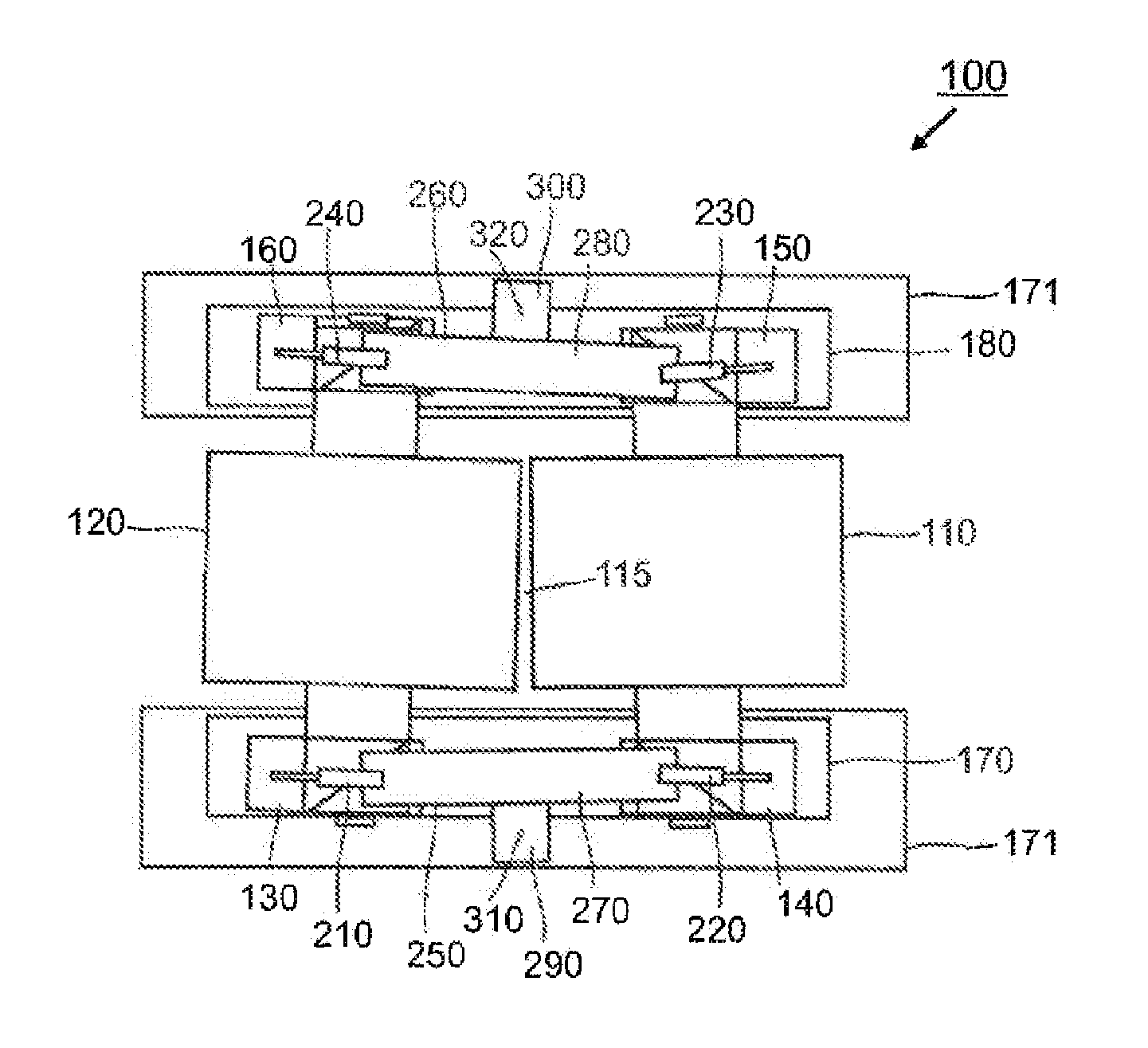
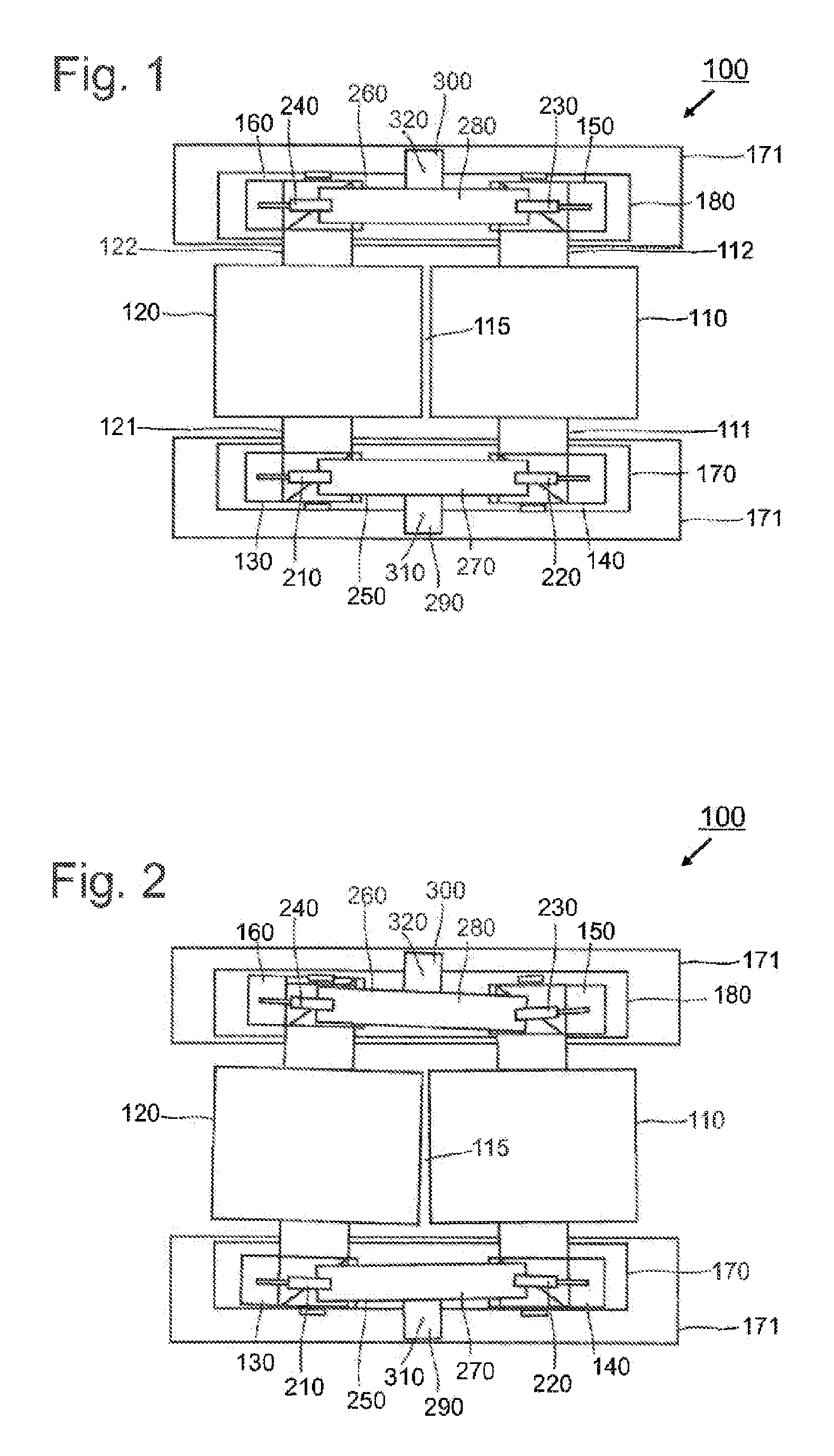
[0019]In FIG. 1, an inventive roller press 100 is depicted in a view from above (parts of a machine frame are blanked out for better representation of the individual parts). In this roller press 100, a first roll 110 is rotatably mounted in the roller press 100 with the aid of shafts III and 112. A second, adjacent roll 120, which for its part is rotatably mounted via shafts 121 and 122 in the roller press, is disposed in the roller press 100, with the formation of a roll gap 115 to be centered. During operation of the roller press 100, the two rolls 110 and 120 are driven in counter rotation, so that the grinding stock delivered from above to the roll gap 115 is drawn into the roll gap 115.

[0020]The mounting of the rolls 110 and 120 in the roller press 100 is realized via fixed bearings disposed in the fixed bearing housings 130 and 140 and via loose bearings disposed in the loose bearing housings 150 and 160, which in the roller press 100 lie opposite the fixed bearing housings 13...


PUM


Abstract

A roller press for the pressure treatment or compaction of granular material, having at least two rolls formed as freely rotating rolls, in each case rotatably mounted in a machine frame by a shaft, driven in opposite directions and separated from one another by a roll gap. The shafts of the rolls are accommodated in bearing housings movably mounted in the machine frame and in each case two bearing housings arranged on one side of the rolls and belonging to different rolls are connected to each other via at least one pressure cylinder. The connection between the bearing housings in each case has at least one torque balance. In this way, the structure of a roller press having roller centering is simplified and can be produced more cost-effectively.

Description

BACKGROUND OF THE INVENTION[0001]The invention relates to a roller press for the pressure treatment or compaction of granular material, having at least two rolls, configured as freely rotating rolls, which are respectively rotatably mounted in a machine frame via a shaft, are driven in counter rotation and are separated from one another by a roll gap, wherein the shafts of the rolls are accommodated in bearing housings movably disposed in the machine frame, and wherein in each case two bearing housings disposed on one side of the rolls and belonging to different rolls are connected to each other via at least one pressure cylinder.[0002]For the centering of the roll gap in roller presses for the pressure treatment or compaction of granular material, the rolls of the roller press are generally held by large-sized hydraulic drives in their desired position in order that, on the one hand, the pressure in the roll gap between the rolls is maintained and, on the other hand, as a result of...

Claims


Application Information

Patent Timeline
IPC IPC(8): B30B3/04B30B15/00
CPCB02C4/32B30B15/00B30B15/04B30B3/04
Inventor FRANGENBERG, MEINHARD
Owner KHD HUMBOLDT WEDAG GMBH
Why Eureka
Try Eureka