Fiber orienting technology for a grinding machine

Active Publication Date: 2013-04-25
FORMTEC
View PDF11 Cites 19 Cited by
  • Summary
  • Abstract
  • Description
  • Claims
  • Application Information

AI Technical Summary

Benefits of technology

[0013]It is an object of the present invention for the fiber orientation technology to reduce the release and mixing of myosin with actin. It is an object of the present invention for the fiber orientation technology

Problems solved by technology

Current forming technology relies on high pressure, speed and complicated material flow pathways which produce

Method used


Image

  • Fiber orienting technology for a grinding machine
  • Fiber orienting technology for a grinding machine
  • Fiber orienting technology for a grinding machine

Examples


Embodiment Construction

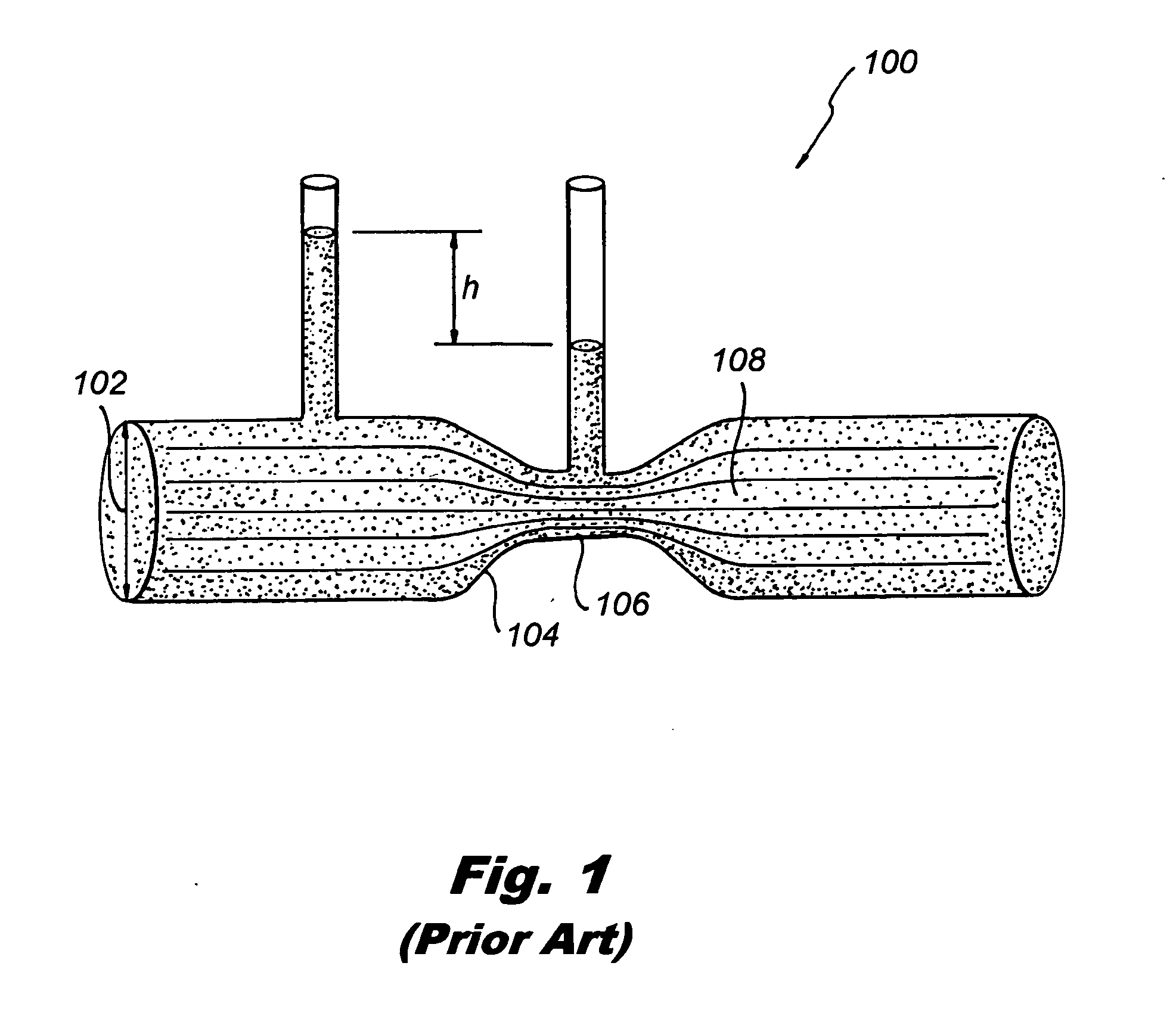
[0044]FIG. 1 shows a prior art venturi 100 comprising a diameter 102 angle transition 104, throat length 106 and discharge 108.

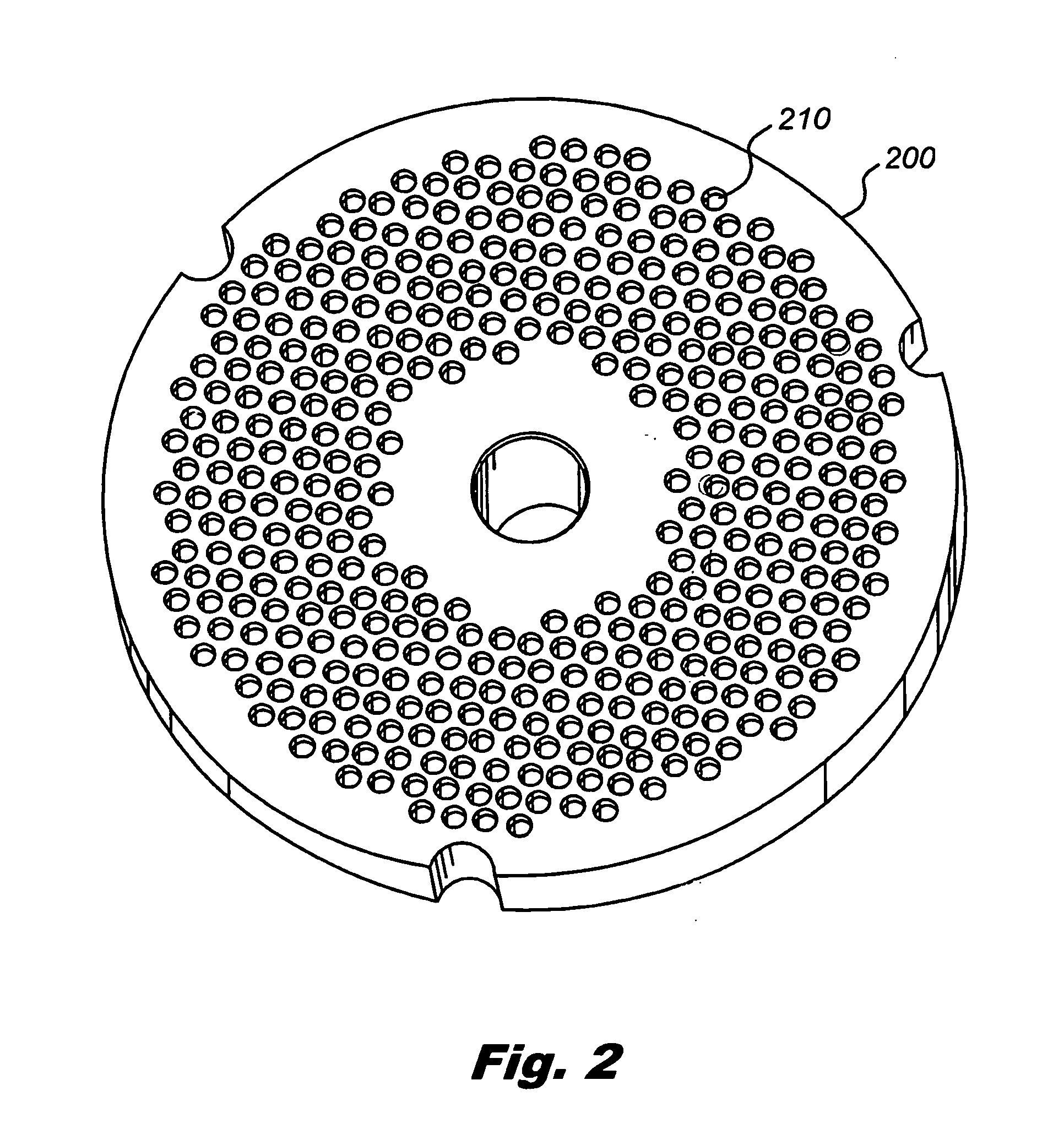
[0045]FIG. 2 shows an orifice plate 200 having apertures 210.

[0046]FIG. 3 shows a magnified view of the orifice plate 200 showing the apertures 210.

[0047]FIG. 4 shows the orifice plate 200 having the apertures 210. The apertures comprising a sphere section 212 and a cylinder section 214.

[0048]FIG. 5 shows a magnified view of the apertures 210 having a spherical section 212 and a cylinder section 214.

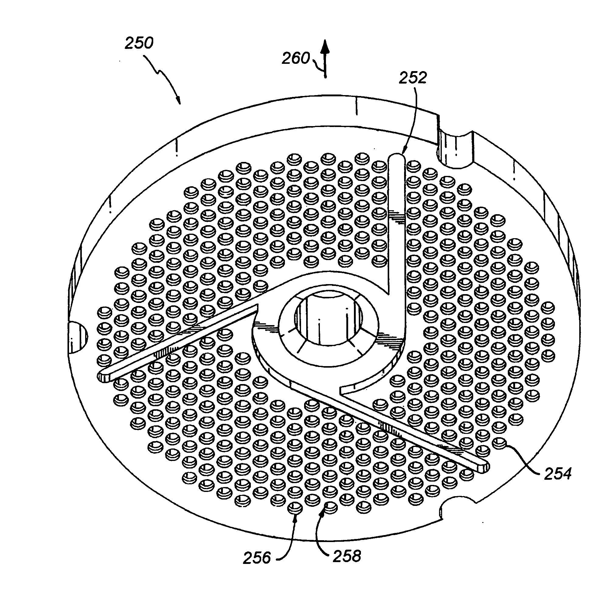
[0049]FIG. 6 shows a grinder plate 250 having a bone collection slots 252, and orifices 254 which are comprised of a spherical diameter 256 and a cylindrical diameter 258. The arrow 260 shows the direction of the meat flow.

[0050]FIG. 7 shows a bone collector tube 270 which is comprised of a waste tube 272, waste auger 274, FOT bone extraction insert 276 which is comprised of a spherical section 278 and a cylindrical section 280.

[0051]The present invention relates...


PUM


Abstract

An apparatus and method for accelerating food product and decreasing pressure of the product in order to cause the product to be stretched aligning the fibers of the product.

Description

RELATED APPLICATIONS[0001]The present application is a continuation-in-part of pending application Ser. No. 13 / 374,441 filed Dec. 29, 2011, Ser. No. 13 / 374,417, filed Dec. 27, 2011, Ser. No. 13 / 374,422, filed Dec. 27, 2011, Ser. No. 13 / 374,421, filed Dec. 27, 2011 and Ser. No. 13 / 374,423, filed Dec. 27, 2011 which all are a continuation-in-part of application Ser. No. 13 / 199,910 filed on Sep. 12, 2011,FIELD OF THE INVENTION[0002]The present invention relates to an apparatus and method for accelerating food product and a decrease in pressure of the product in order to cause the product to be stretched, aligning the fibers of the product.BACKGROUND OF THE INVENTION[0003]Current forming technology relies on high pressure, speed and complicated material flow pathways which produce a product lacking in quality. High pressure works the meat cells, the higher the pressure the more massaging, squeezing and turbulence of the meat cells takes place. High speed combined with a complicated flow...

Claims


Application Information

Patent Timeline
IPC IPC(8): B02C18/30B02C23/08B02C18/36
CPCB02C18/30B02C2018/308B02C23/08B02C18/365
Inventor WOLFF, JAMES B.
Owner FORMTEC
Why Eureka
Try Eureka