Lighting circuit for light emitting element and illumination apparatus including same

Inactive Publication Date: 2013-05-23
PANASONIC INTELLECTUAL PROPERTY MANAGEMENT CO LTD
View PDF3 Cites 6 Cited by
  • Summary
  • Abstract
  • Description
  • Claims
  • Application Information

AI Technical Summary

Benefits of technology

The present invention provides a lighting circuit for a light emitting element that performs burst dimming and suppresses the generation of audible sound from the light emitting element. This is achieved by using a fundamentally high frequency that is equal to or higher than the frequency at the maximum sound pressure level in the audible frequency range, and ensuring that the harmonic sound pressure levels do not exceed the maximum sound pressure level. This results in a low total sound pressure level when generated by using the PWM dimming signal of the square wave obtained by the summation of AC wave signals including the fundamental wave and harmonics of different frequencies that are integer multiples of the fundamental frequency of the fundamental wave. Additionally, using a high fundamental frequency exceeding the audible frequency range can also be avoided to suppress the generation of audible sound from the light emitting element.

Problems solved by technology

For example, in case of using an organic EL element as the light emitting element, it is problematic that audible sound (noise) is generated from the light emitting element when the frequency of a signal for performing the burst dimming is about 1 kHz.
However, it is difficult and expensive to stably operate the circuit which generates such inaudible high frequency signal.

Method used


Image

  • Lighting circuit for light emitting element and illumination apparatus including same
  • Lighting circuit for light emitting element and illumination apparatus including same
  • Lighting circuit for light emitting element and illumination apparatus including same

Examples


first embodiment

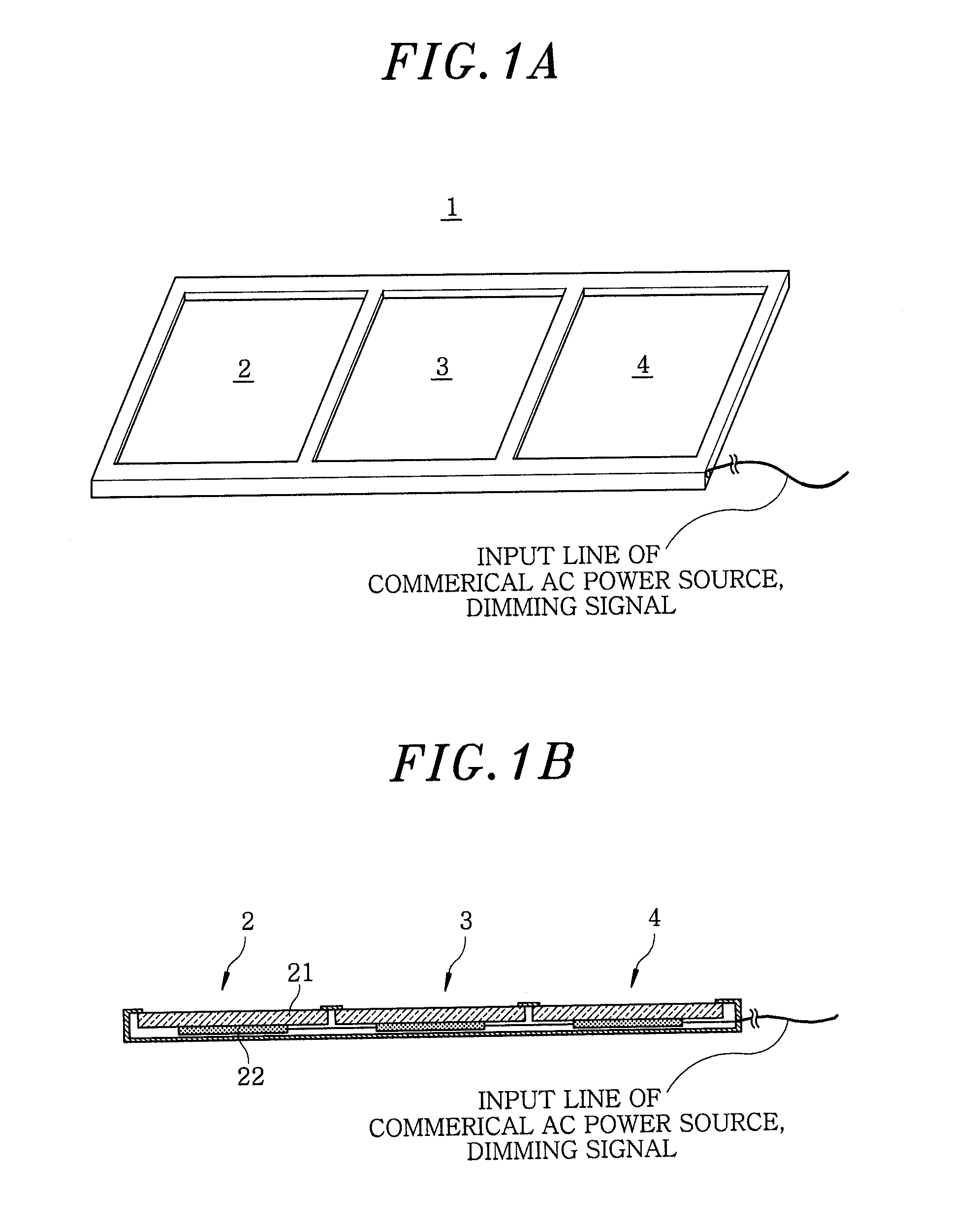
[0026]FIGS. 1A and 1B show an illumination apparatus 1 in accordance with a first embodiment of the present invention. FIG. 1A is a perspective view of the illumination apparatus 1 fixed to a ceiling, wall, floor, stand or the like. The illumination apparatus 1 includes three light emitting panels 2, 3 and 4, each having a light emitting surface oriented upward in FIG. 1A. FIG. 1B is a cross-sectional view of the illumination apparatus 1. The light emitting panels 2, 3 and 4 have the same configuration.

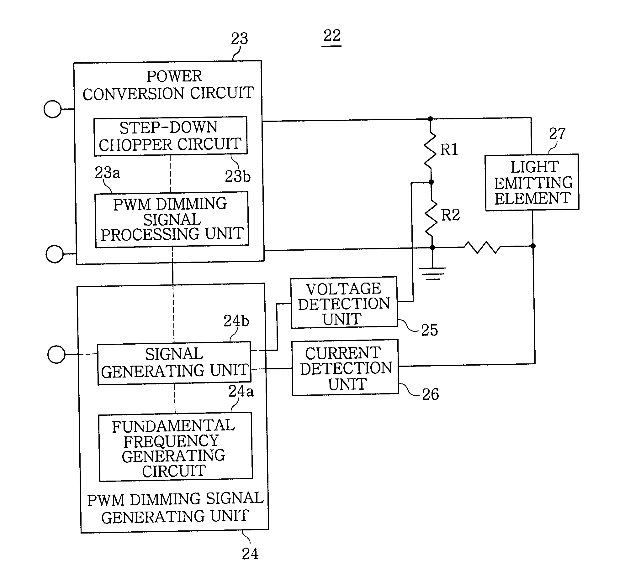
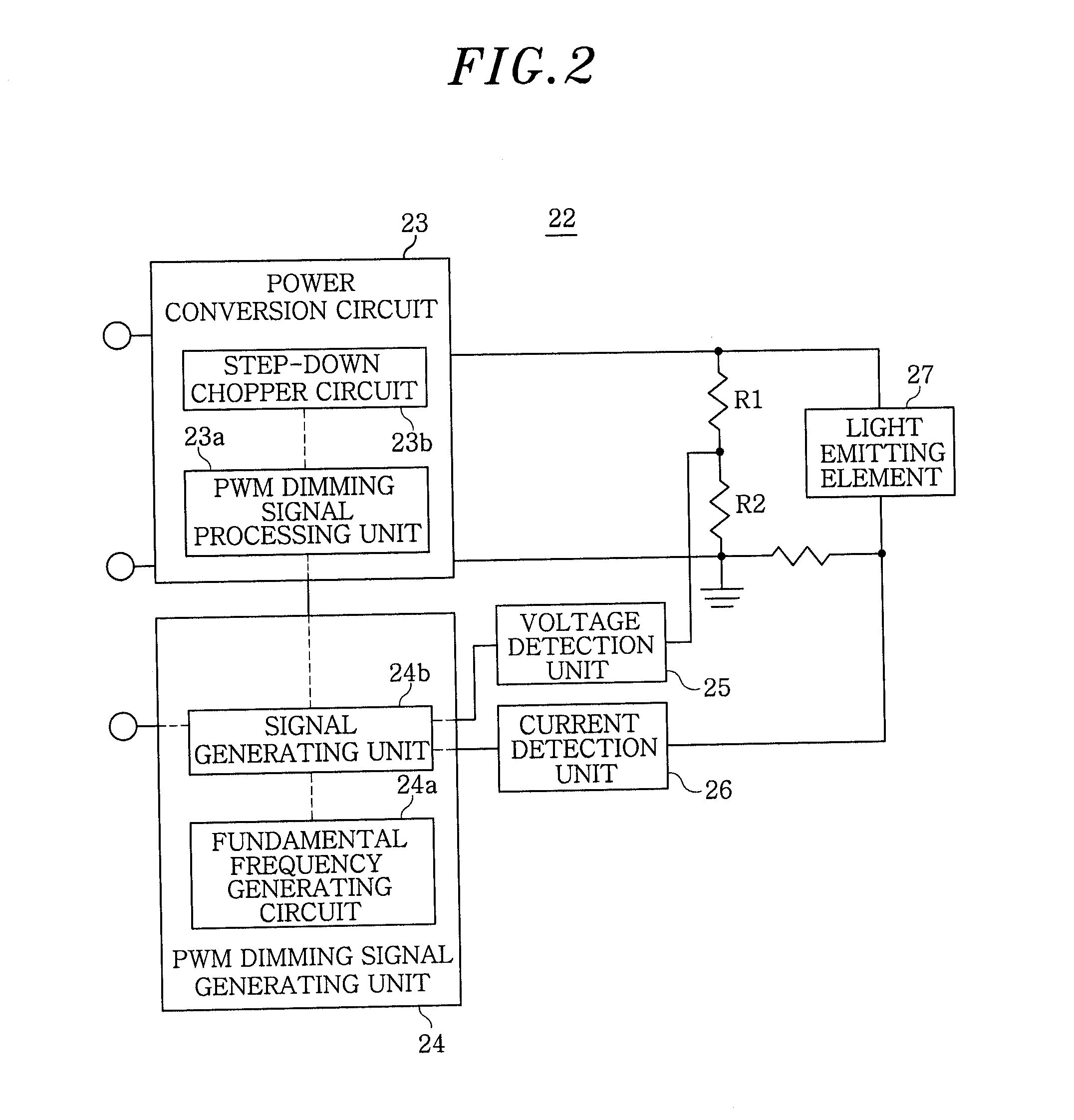
[0027]In the following, a description will be made using the light emitting panel 2 as an example. The light emitting panel 2 includes an organic EL light emitting element 21 and a light-emitting-element lighting circuit (hereinafter, simply referred to as lighting circuit) 22 which performs a burst dimming of the light emitting element 21. The lighting circuit 22 is connected to a commercial AC power source having a frequency of 50 Hz or 60 Hz, and a cable to which the dimming signal...

second embodiment

[0038]The lighting circuit in accordance with a second embodiment of the present invention is configured to switchably use a plurality of fundamental frequencies, and generate the PWM dimming signal by selecting the fundamental frequency, at which the sound pressure level of the audible sound is the lowest, for each duty ratio corresponding to the input dimming signal.

[0039]FIG. 5 is a circuit diagram of a light-emitting-element lighting circuit 22a in accordance with a second embodiment of the present invention. The same reference numerals will be given to the same components as those of the light emitting element lighting circuit 22 in accordance with the first embodiment of the present invention, and a redundant description will be omitted. The lighting circuit 22a includes the power conversion circuit 23, a PWM dimming signal generating unit 28, the voltage detection unit 25, the current detection unit 26, and the light emitting element 27.

[0040]The PWM dimming signal generating...


PUM


Abstract

A light-emitting-element lighting circuit for dimming a light emitting element by a PWM dimming signal of a duty ratio corresponding to an input dimming signal is provided. The lighting circuit includes a PWM dimming signal generating unit which generates the PWM dimming signal by performing a summation of AC wave signals including a fundamental wave and harmonics of different frequencies that are integer multiples of a fundamental frequency of the fundamental wave. The fundamental frequency is equal to or higher than a frequency, at which a sound pressure level is at maximum, in an audible frequency range in a correlation spectrum between the sound pressure level generated from the light emitting element and a frequency of an AC wave signal inputted to the light emitting element.

Description

FIELD OF THE INVENTION[0001]The present invention relates to a lighting circuit for a light emitting element such as an organic electroluminescence (EL) element or the like, and an illumination apparatus including the lighting circuit.BACKGROUND OF THE INVENTION[0002]Conventionally, there has been known a lighting circuit for a light emitting element such as an organic EL element or the like, which is configured to generate a PWM dimming signal having a duty ratio corresponding to a light emission level specified by a dimming signal, and perform the dimming control.[0003]For example, Japanese Patent Application Publication No. 2009-54425 describes a lighting circuit configured to perform a so-called burst dimming to stop the light emission of the light emitting element during the OFF period of the PWM dimming signal.[0004]For example, in case of using an organic EL element as the light emitting element, it is problematic that audible sound (noise) is generated from the light emittin...

Claims


Application Information

Patent Timeline
IPC IPC(8): H05B37/02H05B44/00
CPCH05B37/02H05B33/08H05B33/0818H05B45/327H05B44/00
Inventor HAYASHI, YOHEIKONISHI, HIROFUMIMISHIMA, MASANORIOKAWA, MASANAO
Owner PANASONIC INTELLECTUAL PROPERTY MANAGEMENT CO LTD
Why Eureka
Try Eureka