Micro-gyroscope and method for operating a micro-gyroscope

a micro-gyroscope and micro-gyroscope technology, applied in the field of micro-gyroscopes, can solve the problems of the large installation space of the two sensor devices disposed adjacent to the gyroscope, and achieve the effect of reducing the installation height, compact construction, and simplifying the capture of signals and driving the drive masses

Active Publication Date: 2013-06-27
HANKING ELECTRONICS LTD
View PDF6 Cites 4 Cited by
  • Summary
  • Abstract
  • Description
  • Claims
  • Application Information

AI Technical Summary

Benefits of technology

[0011]A substantial advantage of the present invention is that the sensor masses are deflected within the X-Y plane in which the drive mass is also disposed. Installation space outside of the X-Y plane is not required for this sensor. In addition to the small area required by the micro-gyroscope according to the invention on the substrate, a very low installation height is hereby made possible by the micro-gyroscope. The two planes in which the first and second sensor device are disposed can be very close to each other, because no components are displaced out of said plane. The sensor according to the invention is thus very compact in construction, but still reliable with respect to the measurements thereby produced.
[0012]The first and second drive mass are preferably attached to the same anchors on the substrate. A compact design is also possible because the drive masses of the first and second sensor device use at least partially the same mountings. One anchor thus extends over a plurality of planes in the Z-direction, so to speak. The anchor is attached at one end to the substrate and allows the individual drive masses of the sensor device to be disposed at different distances from the substrate. Of course, however, each sensor device can have a dedicated mounting and anchor.
[0013]In an advantageous embodiment of the invention, the sensor elements are electrode pairs, wherein one electrode is connected to the substrate in a stationary manner, and the other electrode is disposed on the sensor mass that can be displaced in the direction of the Y-axis. The stationary electrodes can thereby be stationary and disposed between the substrate and the first sensor device, between the first and second sensor device, and / or between the second sensor device and a further layer disposed above the second sensor device, such as a cover of the micro-gyroscope.
[0014]It is particularly advantageous, when the drive masses are operated in antiphase to each other, if the electrode pairs of the first sensor device have the opposite polarity of the electrode pairs of the second sensor device. After the two sensor mass are deflected in opposite directions to each other in case of an opposite displacement of the drive masses when a Z rate of rotation occurs, it is advantageous if each of the electrode pairs also has the opposite polarity. This results in comparable signals that largely correspond to each other, in order to indicate a correct deflection of the sensor masses.
[0015]In order to obtain a further improvement of the micro-gyroscope according to the invention, further sensor devices can also be associated with the first and second sensor devices. It is therefore advantageously possible that the micro-gyroscope comprises a third and fourth sensor device, implemented identically to the first and second sensor device. Said third and fourth sensor devices can either be disposed above the first and second sensor device again, so that not only two planes, but a plurality of planes of sensor devices are present. It is particularly advantageous, however, if the third and fourth sensor device are disposed in the planes of the first and second sensor device. The required area for the sensor device on the substrate is indeed thereby increased, but the capture of the signals and driving of the drive masses is thereby simplified.
[0016]Either additional rates of rotation can be captured by the further sensor devices, or, particularly advantageously, a further verification of the sensor signal and additional robustness of the sensor can be obtained. This is particularly the case if the first and second sensor device are connected to the third and fourth sensor device by means of a coupling spring. The drive masses disposed adjacent to each other in one plane thus oscillate either identically or in opposition, and the drive masses disposed diagonally to each other can be driven to oscillate either identically or in opposition, that is, in phase or in antiphase. A plurality of sensor signals is thereby obtained that can be compared to each other or differentiated, whereby the accuracy of the micro-gyroscope is significantly increased.

Problems solved by technology

A disadvantage of said type of micro-gyroscope is the large installation space required for the two sensor devices disposed adjacent to each other on the substrate.

Method used


Image

  • Micro-gyroscope and method for operating a micro-gyroscope
  • Micro-gyroscope and method for operating a micro-gyroscope
  • Micro-gyroscope and method for operating a micro-gyroscope

Examples


Embodiment Construction

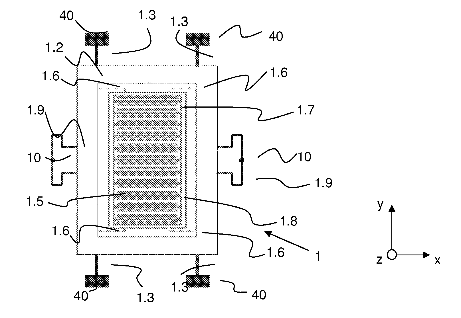
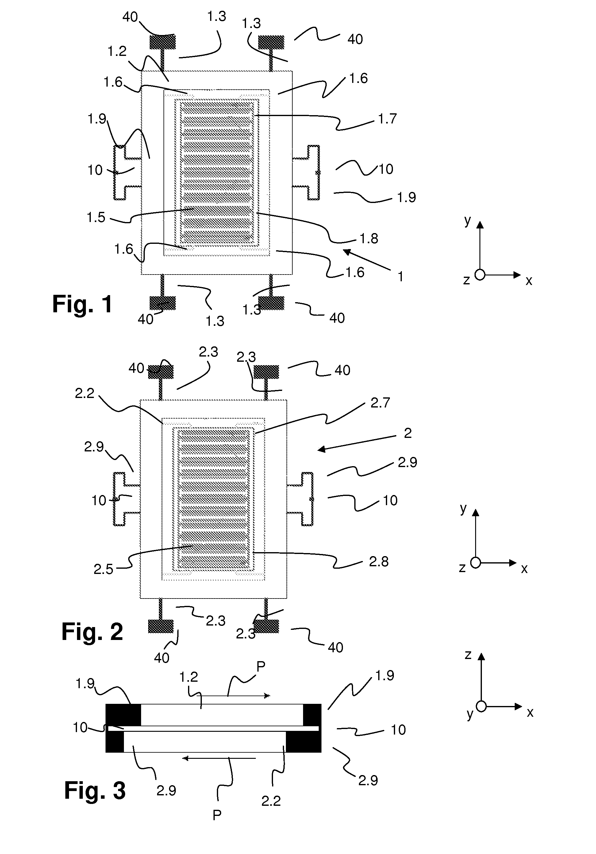
[0025]FIG. 1 shows a sketch of a plan view of a first sensor device 1. The first sensor device 1 comprises a frame-shaped drive mass 1.2 that is attached to an anchor 40 by means of anchor springs 1.3. The anchor 40, in turn, is attached to a substrate (not shown) below the drive mass 1.2. The drive mass 1.2 is driven to oscillate in the X-direction by means of drive elements (not shown), such as comb electrodes. A sensor mass 1.5 is disposed in the interior of the frame of the drive mass 1.2. The sensor mass 1.5 is connected to the drive mass 1.2 by means of springs 1.6.

[0026]While the anchor springs 1.3 allow displaceability of the drive mass 1.2 in the X-direction, but said mass is rigidly constructed in the Y-direction and Z-direction, the spring 1.6 is designed such that it does indeed move the sensor mass 1.5 together with the drive mass 1.2 in the X-direction, but allows the sensor mass 1.5 to be deflected in the Y-direction when a Coriolis force occurs. The spring 1.6 is als...


PUM


Abstract

A micro-gyroscope for determining a rate of rotation about a Z-axis includes a substrate and two sensor devices each of which comprises at least one drive mass, at least one anchor, drive elements, at least one sensor mass and sensor elements. The drive mass is mounted linearly displaceably in the direction of an X-axis, and can be driven in an oscillatory manner with respect to the X-axis. The sensor mass is coupled to the drive mass by means of springs. The sensor mass is displaceable in the Y-direction, and sensor elements detects a deflection of the sensor mass in the Y-axis. The two sensor devices are disposed parallel to each other and one above the other in the direction of the Z-axis, and the drive mass in these two sensor devices are coupled to each other by means of a coupling spring.

Description

CROSS REFERENCE TO RELATED APPLICATIONS[0001]The application claims the benefit of German Application Serial No. 10 2011 057 032.2, entitled “Mikro-Gyroskop and Verfahren zum Betreiben eines Mikro-Gyroskops”, filed on Dec. 23, 2011, the subject matter of which is incorporated herein by reference.BACKGROUND[0002]A. Technical Field[0003]The present invention relates to a micro-gyroscope for determining the rate of rotation about a Z-axis, having a substrate and having a first and second sensor device, wherein each sensor device comprises at least one drive mass disposed parallel to the substrate and at least one anchor by means of which the drive mass is attached to the substrate. At least one anchor spring is disposed between the anchor and the drive mass so that the drive mass is mounted linearly displaceably in the direction of an X-axis, and rigidly in the direction of a Y-axis and a Z-axis. Drive elements by means of which the drive mass can be driven in an oscillatory manner in ...

Claims


Application Information

Patent Timeline
Patent Type & Authority Applications(United States)
IPC IPC(8): G01C19/56
CPCG01C19/56G01C19/5762G01C19/5747G01C19/5712
Inventor ROCCHI, ALESSANDROGIAMBASTIANI, ADOLFO
Owner HANKING ELECTRONICS LTD
Why Eureka
Try Eureka