

Charging apparatus
a charging apparatus and charging technology, applied in the direction of transportation and packaging, indicating/monitoring circuit, and battery arrangement for several simultaneous batteries, can solve the problems of complicated operation for users and the inability to start the mobile terminal placed later, and achieve the effect of quick starting of the higher priority of charging and easy change of the charge order
Inactive Publication Date: 2013-07-04
SONY MOBILE COMM INC
View PDF1 Cites 18 Cited by
- Summary
- Abstract
- Description
- Claims
- Application Information
AI Technical Summary
Benefits of technology
The invention is about a charging apparatus that allows multiple mobile terminals to be charged simultaneously. The invention allows for easy switching of charging order, so the mobile terminal with higher priority can be quickly charged.
Problems solved by technology
However, even in a case where the user wants to charge a specific one of the mobile terminals as soon as possible after the placement order of the mobile terminals has been determined, the charging of a mobile terminal placed later is not started until the charging of a mobile terminal placed earlier is completed.
This is a complicated operation for the user.
Method used
View moreImage
Smart ImageViewing Examples

Examples
first exemplary embodiment (
1. First Exemplary Embodiment (Example of Changing Charge Order by Touching Icon),
second exemplary embodiment (
2. Second Exemplary Embodiment (Example of Changing Charge Order by Tapping Mobile Terminal or Writing Charge Order on Touch Panel),
third exemplary embodiment (
3. Third Exemplary Embodiment (Example of Changing Charge Order by Changing Arrangement of Mobile Terminals Placed on Charging Pad),
[0038]4. Fourth Exemplary Embodiment (Example of Performing Charging While Keeping Charge Order Set in Advance in Case Where Mobile Terminal Falls from Charging Pad and Is Replaced on Charging Pad), and
5. Modification.
Login to View More PUM
 Abstract
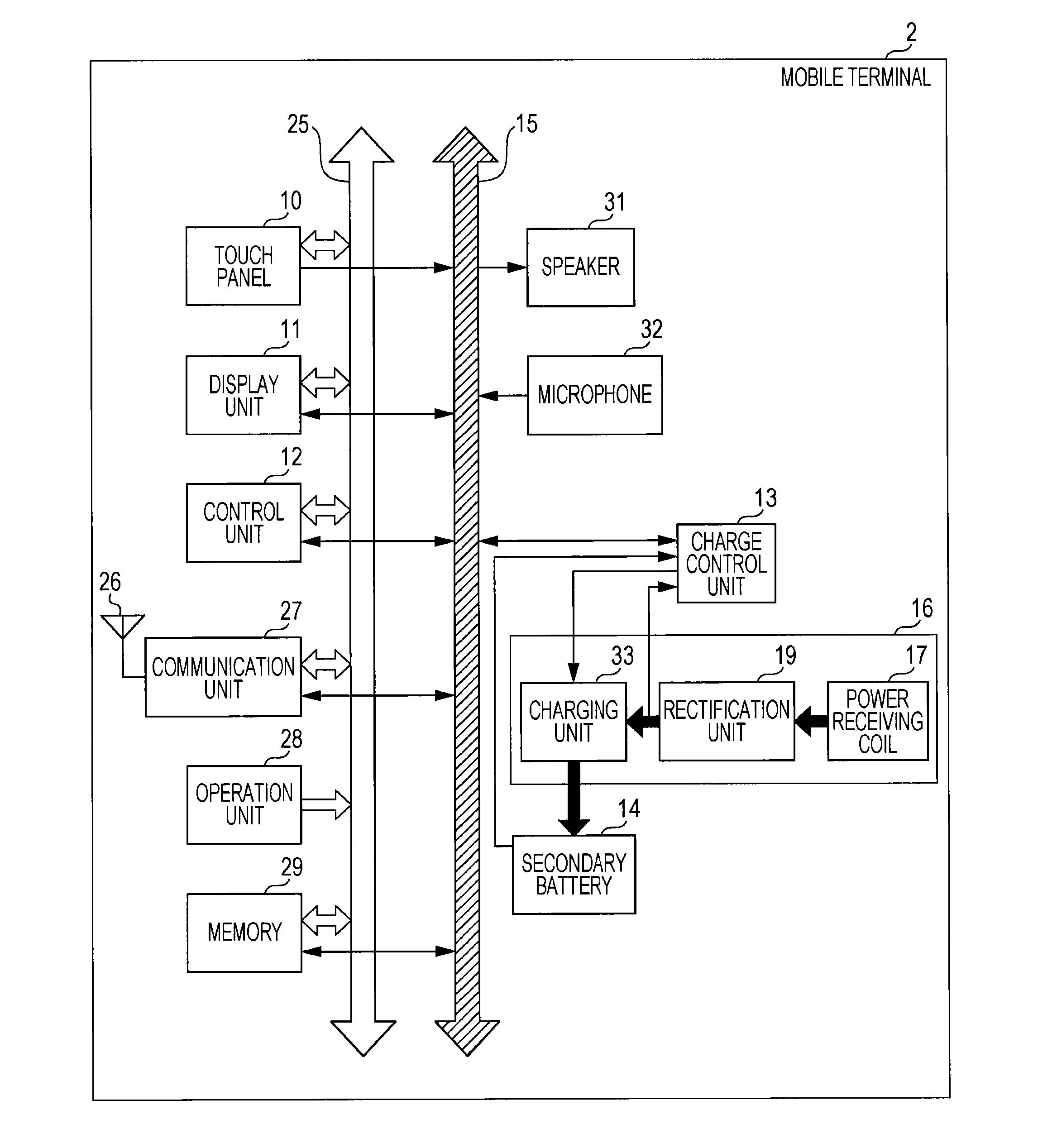
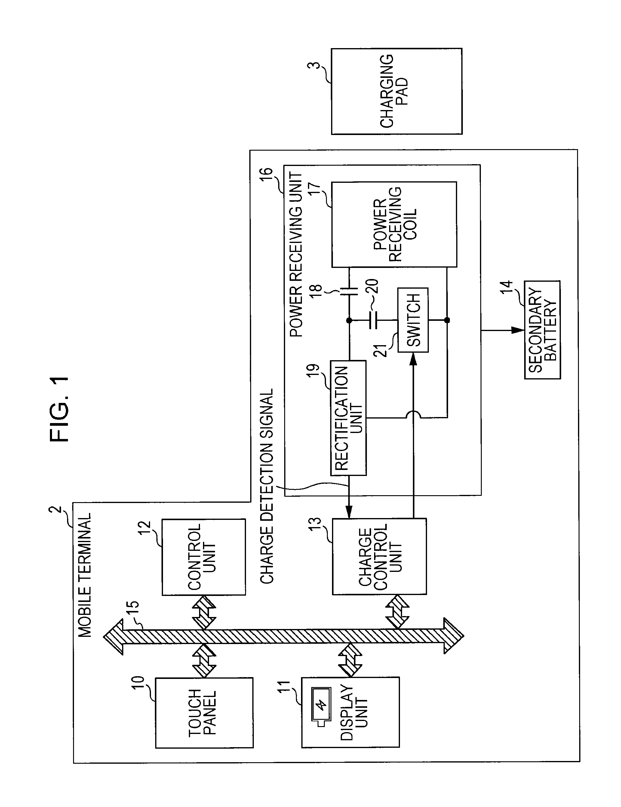
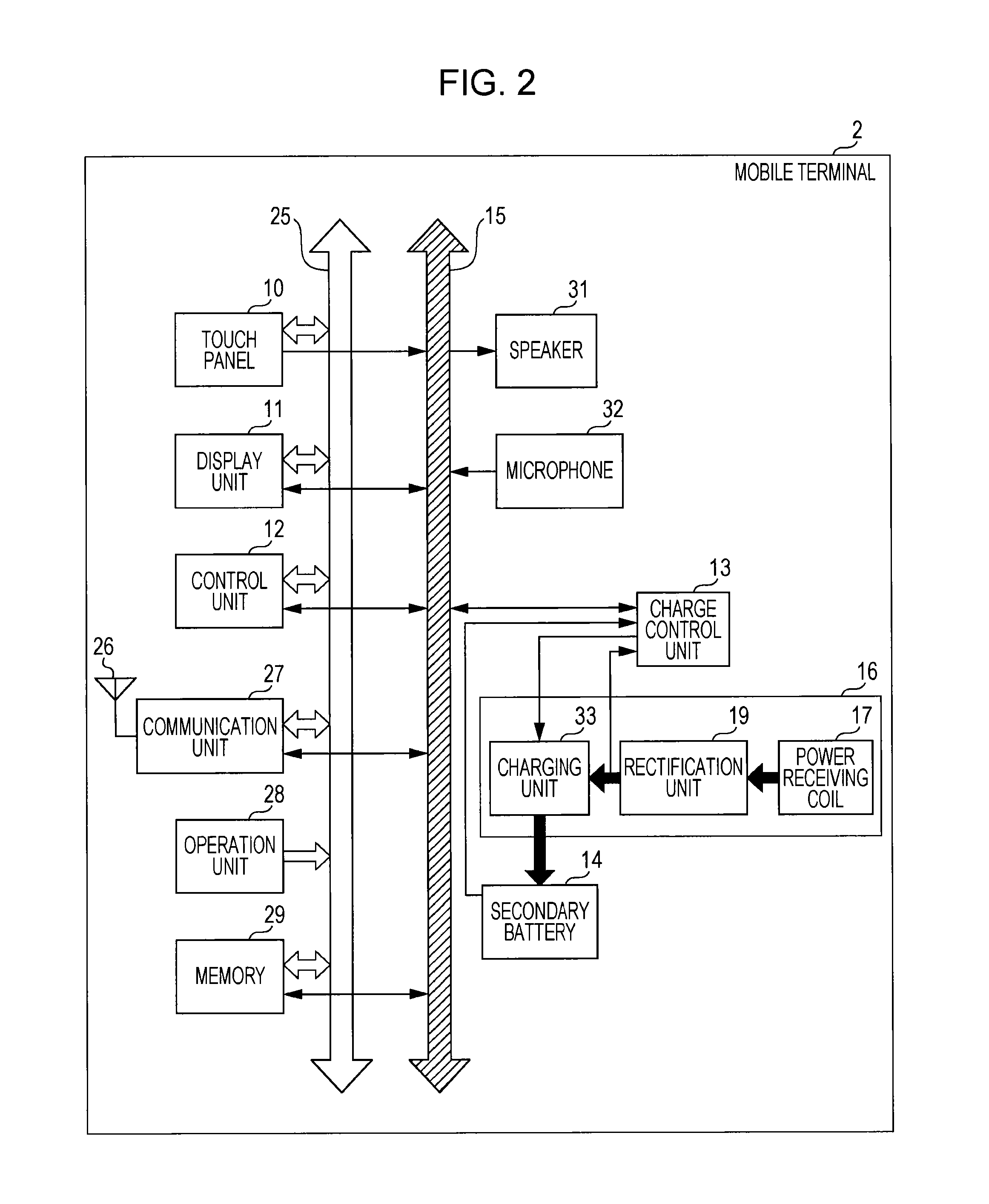
A charging apparatus including a mounting portion on which a plurality of information processing apparatuses are mounted, a power transmission unit that transmits power in a non-contact manner to each of the plurality of information processing apparatuses placed on the mounting portion, and a control unit that receives a charge order instruction from at least one of the plurality of information processing apparatuses, and controls the power transmission unit to transmit power to each of the plurality of information processing apparatuses in an order determined based on the received charge order instruction.
Description
CROSS REFERENCE TO RELATED APPLICATION[0001]The present application claims the benefit of the earlier filing date of U.S. Provisional Patent Application Ser. No. 61 / 581,440 filed on Dec. 29, 2011, the entire contents of which is incorporated herein by reference.BACKGROUND[0002]1. Field of the Disclosure[0003]The present disclosure relates to a charging apparatus for charging a secondary battery installed in a mobile terminal with a wireless feeding method.[0004]2. Description of Related Art[0005]In recent years, charging apparatuses capable of charging a secondary battery in a battery pack installed in an information processing terminal such as a mobile telephone with a standardized wireless feeding method have been provided.[0006]An exemplary operation of a charging apparatus in the related art will be described with reference to FIG. 20.[0007]FIG. 20 is a diagram illustrating a state in which a charging pad 102 in the related art charges a plurality of mobile terminals 101-1 to 10...
Claims
Login to View More Application Information
Patent Timeline
 Patent Type & AuthorityApplications(United States)
IPC IPC(8): H02J7/00
CPCH02J7/0013H02J5/005H02J7/025H02J7/0027H02J7/0044H02J7/0021H02J50/90H02J7/0048H02J7/0047H02J2310/22H02J50/12H02J50/80
InventorSUZUKI, KATSUYASUZUKI, KUNIHARUSAKAI, DAISUKE
OwnerSONY MOBILE COMM INC