Adaptable remote radio unit mounting frame

a technology for remote radio units and mounting frames, which is applied in the field of new, compact and versatile mounting frames for telecom units, can solve the problems of limiting future growth and not intended summary, and achieve the effects of compact and versatile mounting of telecom equipment, saving a considerable amount of economic resources, and condensing the footprint of telecom equipmen

Inactive Publication Date: 2013-08-22
MATHEWSON RICHARD
View PDF9 Cites 16 Cited by
  • Summary
  • Abstract
  • Description
  • Claims
  • Application Information

AI Technical Summary

Benefits of technology

[0014]In one exemplary embodiment, the new adaptable mounting frame is a four-sided frame which has one or more doors, and which is configured to permit compact and versatile mounting of telecom equipment. Thus, an advantage is that it condenses the footprint of the telecom equipment, which saves a considerable amount of economic resources. Another advantage is that this is a versatile design because, among other things, it can be mounted in the middle of the room, against a wall, indoor, outdoor, and so on, and because it can also be expanded in width, depth, and / or height. Thus, this is a versatile and compact mounting frame that solves the known problems with the prior art described above.
[0015]Again, the wireless cell site equipment is changing from a few large equipment cabinets to many small cabinets and miscellaneous equipment which includes RRU, OBIF, and PBC-02. The disclosed frame will be able to reduce the foot print of the new wireless equipment by arranging the equipment in a way which utilizes all horizontal and vertical space.
[0016]In addition, again, the space restraints in the field of so called leased area limit future growth. The disclosed frame can be built in various shapes and sizes as described below. Thus, by using the new adaptable frame, wasted or dead space is eliminated, any available space is utilized and equipment count is maximized. By fully utilizing the leased space the wireless carriers can save money by not having to expand leased area to accommodate new wireless equipment.

Problems solved by technology

Moreover, this Summary is not intended for use as an aid in determining the scope of the claimed subject matter.
In addition, again, the space restraints in the field of so called leased area limit future growth.

Method used


Image

  • Adaptable remote radio unit mounting frame
  • Adaptable remote radio unit mounting frame
  • Adaptable remote radio unit mounting frame

Examples


Embodiment Construction

[0029]What follows is a detailed description of the preferred embodiments of the invention in which the invention may be practiced. Reference will be made to the attached drawings, and the information included in the drawings is part of this detailed description. The specific preferred embodiments of the invention, which will be described herein, are presented for exemplification purposes, and not for limitation purposes. It should be understood that structural and / or logical modifications could be made by someone of ordinary skills in the art without departing from the scope of the invention. Therefore, the scope of the invention is defined by the accompanying claims and their equivalents.

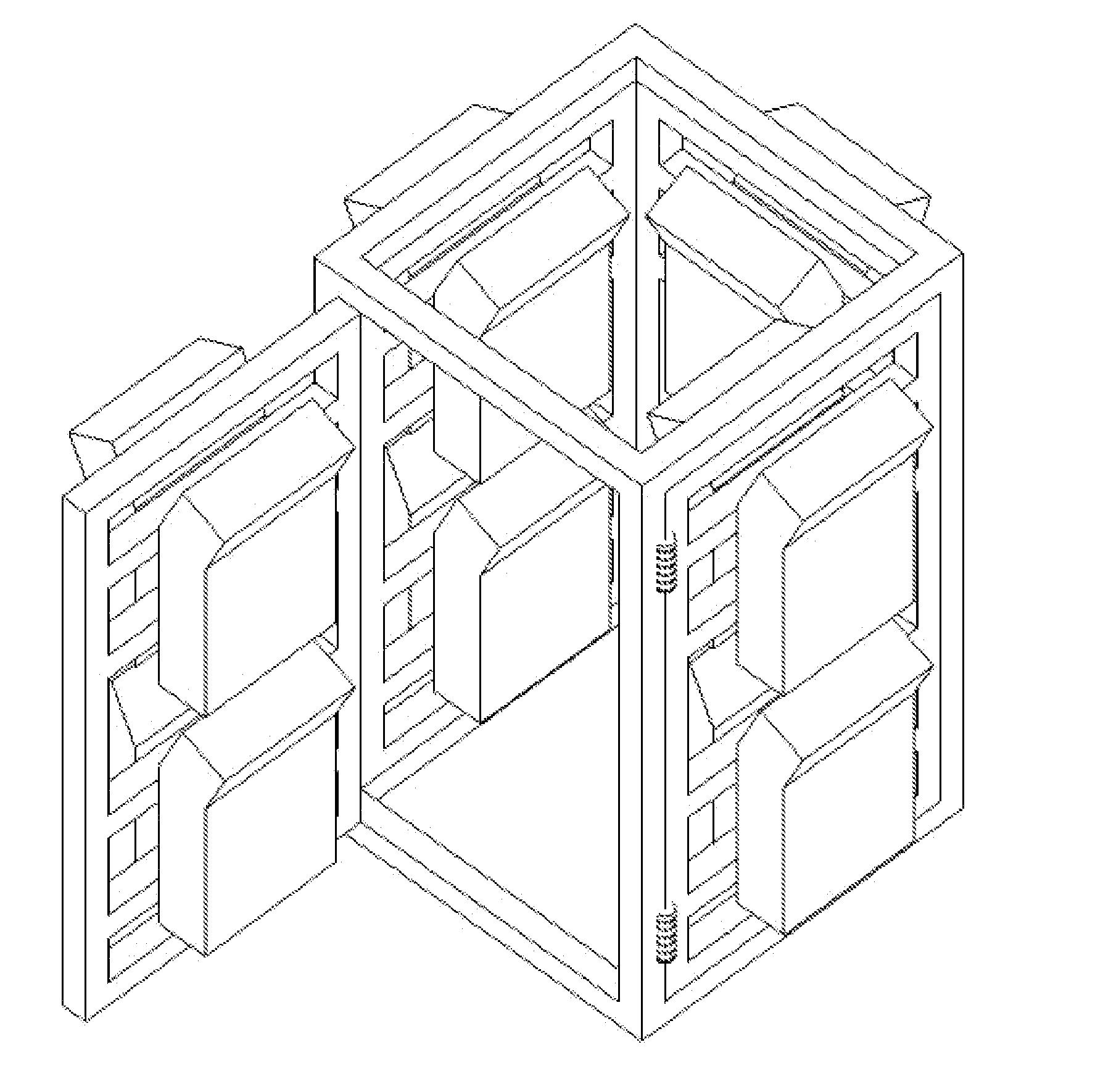
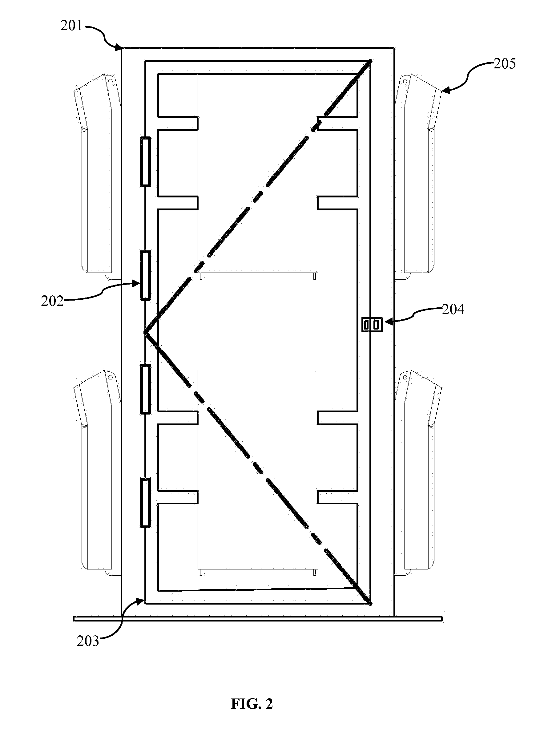
[0030]Referring now to FIGS. 2, 3 and 4, it is shown that the new adaptable mounting frame 400 for telecom units or equipment may be have a shape similar to that of a rectangular prism, which may be made by building a rectangular prism-like skeleton 201, 301, 401, having four vertical members coup...


PUM


Abstract

A prism-like frame for mounting telecom equipment made of a prism-like skeleton, which in turn is made of at least three vertical members coupled with at least six horizontal members, and at least one open panel connected to at least one lateral side of the skeleton, wherein the panel includes at least two horizontal members arranged apart from each other and away from the bottom and top of the skeleton.

Description

CROSS-REFERENCE TO RELATED APPLICATIONS[0001]Not ApplicableSTATEMENT REGARDING FEDERALLY SPONSORED RESEARCH OR DEVELOPMENT[0002]Not ApplicableREFERENCE TO SEQUENCE LISTING, A TABLE, OR A COMPUTER PROGRAM LISTING COMPACT DISC APPENDIX[0003]Not ApplicableBACKGROUND OF THE INVENTION[0004]1. Field of the Invention[0005]The invention relates generally to mounting frames for telecom units and more particularly to a new, compact and versatile mounting frame for telecom units.[0006]2. Description of the Related Art[0007]The wireless cell site equipment is changing from a few large equipment cabinets to many small cabinets and miscellaneous equipment which includes RRU (Remote Radio Unit), OBIF (Optical Basestation Interface), or PBC-02 (Power and Battery Cabinet-02). Furthermore, there are space limitations in the field of so called leased area and they restrain future growth.[0008]There are currently available on the market frames that may be used to mount telecom units or equipment such a...

Claims


Application Information

Patent Timeline
Patent Type & Authority Applications(United States)
IPC IPC(8): A47B81/06
CPCH04Q1/09H05K7/186
Inventor MATHEWSON, RICHARD
Owner MATHEWSON RICHARD
Why Eureka
Try Eureka