Wind-powered light-emitting diode lamp

a light-emitting diode lamp and wind-powered technology, which is applied in the direction of lighting and heating apparatus, greenhouse gas reduction, and power-in-place, can solve the problems of inconvenient operation and high manufacturing cost of lamps, and achieve the effects of convenient connection, efficient power generation, and simple use structur

Inactive Publication Date: 2013-09-12
ZHE JIANG HONG ZHU PLASTIC HARDWARE
View PDF9 Cites 6 Cited by
  • Summary
  • Abstract
  • Description
  • Claims
  • Application Information

AI Technical Summary

Benefits of technology

[0011]A portion of the reflective casing extends outward from the lower cover and is covered by a transparent lamp lid for protecting the LED lamp plate in the reflective casing.
[0012]The vent inlet hole of the wind-powered LED lamp can be conveniently connected with most inflating pumps currently available on the market. Air can enter the lamp through the vent inlet hole of the lower cover to drive the rotor in rotation, which in turn drives the power generating motor in rotation to produce electricity that is stored in the storage battery. The used structure is simple and can more efficiently generate power. Moreover, the vent outlet hole of the upper cover can be connected with an external body that needs to be inflated, so that the body can be inflated and power can be generated simultaneously. Time thus can be saved. Moreover, the present invention can be used repeatedly, which can save energy resource and protect the environment.

Problems solved by technology

However, these lamps are not convenient to operate and expensive to manufacture.

Method used


Image

  • Wind-powered light-emitting diode lamp
  • Wind-powered light-emitting diode lamp
  • Wind-powered light-emitting diode lamp

Examples


embodiment 1

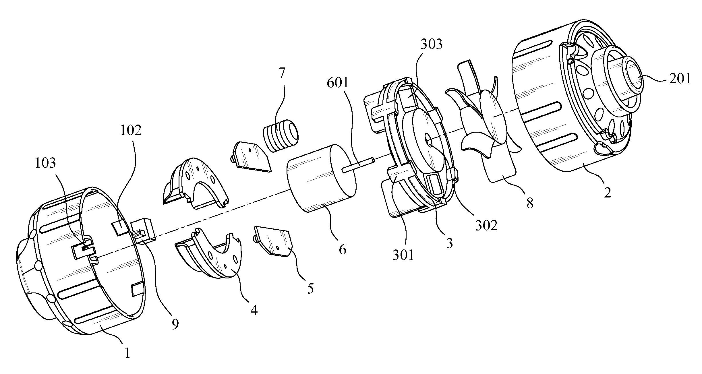
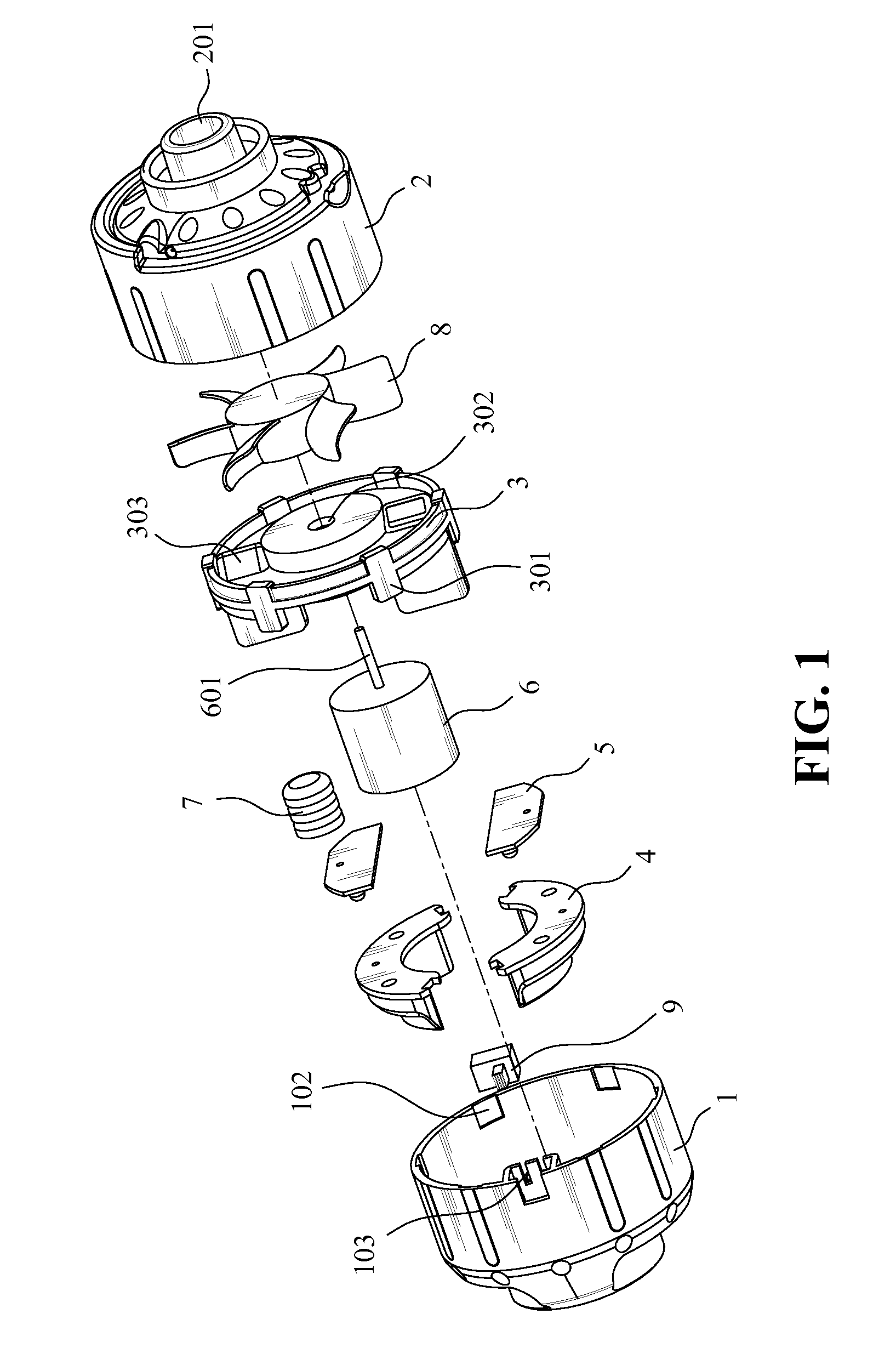
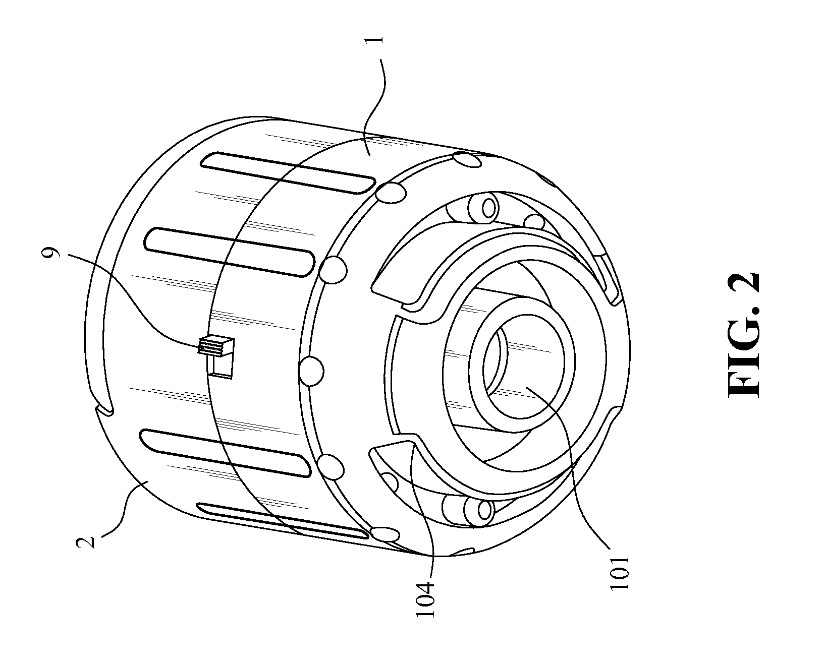
[0021]As shown in FIGS. 1 and 2, a wind-powered light-emitting diode (LED) lamp includes a lower cover 1, a reflective casing 4, an LED lamp plate 5 and an upper cover 2. The lower cover 1 has an outer surface formed with a plurality of mount holes 104 for assembling the reflective casing 4, and a vent inlet hole 101 extending through the outer surface. The mount holes 104 are located at two sides of the vent inlet hole 101. The reflective casing 4 is assembled through an interior of the mount holes 104, and extends outward from the lower cover 1. The LED lamp plate 5 is assembled in the lower cover 1, and is affixed with the reflective casing 4. The upper cover 2 has an outer surface formed with a vent outlet hole 201. The upper cover 2 and the lower cover 1 are assembled to define an interior space, in which are placed a motor fixing frame 3, a power generating motor 6, a rotor 8 provided with blades, and a storage battery 7. The upper and lower covers 2 and 1 respectively have an...

embodiment 2

[0026]As shown in FIGS. 4 and 5, the wind-powered LED lamp is generally similar to the previous embodiment in structure. However, in order to use the lamp as a suspended lamp, the outer surface of the upper cover 2 is formed with symmetrical engaging openings 202 for pivotally connected with two ends of a pull ring 11.

embodiment 3

[0027]As shown in FIGS. 6 and 7, the wind-powered LED lamp is generally similar to the previous embodiment in structure. However, in this embodiment, a portion of the reflective casing 4 extending outward from the lower cover 1, is covered by a transparent lamp lid 10, which is used for protecting the LED lamp plate 5 in the reflective casing 4.


PUM


Abstract

A wind-powered lamp includes lower and upper covers confining a space and having inlet and outlet holes, a reflective casing disposed in the space to extend outward from the inlet hole in the lower cover, a lamp plate affixed to the reflective casing, a fixing frame, a power generating motor, a rotor and a storage battery. The upper and lower covers respectively have an open end defining inlet and out holes, an inner sidewall extending inwardly from the open end. The motor fixing frame has engaging ribs engaging with slots formed on inner side wall to affix the motor fixing frame. The power generating motor is affixed within the fixing frame such that a motor shaft passes through a shaft hole in the fixing frame to connect with the rotor. The power generating motor, the storage battery and the lamp plate are serially and electrically connected to one another.

Description

BACKGROUND OF THE INVENTION[0001]1. Field of the Invention[0002]The present invention relates to a small wind-powered illuminating lamp, and more particularly to a wind-powered light-emitting diode (LED) lamp.[0003]2. The Prior Arts[0004]Wind power is a sustainable energy source that can be used to generate electricity, and implemented as a solution to the lack of energy.[0005]Current outdoor lamps and handheld lamps are usually and manually agitated, using solar power, or electrically chargeable to provide power for illumination. However, these lamps are not convenient to operate and expensive to manufacture.SUMMARY OF THE INVENTION[0006]A primary objective of the present invention is to provide a wind-powered LED lamp that is simple in structure, and easy to use.[0007]To achieve at least the aforementioned objectives, the wind-powered LED lamp of the present invention includes a lower cover, a reflective casing, an LED lamp plate and an upper cover. The lower cover has an outer su...

Claims


Application Information

Patent Timeline
Patent Type & Authority Applications(United States)
IPC IPC(8): F21L13/02
CPCF21L13/02F03D9/10F03D9/11F03D9/25F21Y2115/10Y02E10/72Y02E70/30F21S9/043
Inventor TSAI, JING-HONG
Owner ZHE JIANG HONG ZHU PLASTIC HARDWARE
Why Eureka
Try Eureka