Dental implant system

a dental implant and implant technology, applied in the field of dental implants, can solve the problems of unstable and poorly fitting dental prosthesis, less than satisfactory, and relatively large implants,

a dental implant and implant technology, applied in the field of dental implants, can solve the problems of unstable and poorly fitting dental prosthesis, less than satisfactory, and relatively large implants,

US20130252205A1Inactive Publication Date: 2013-09-26WORTHINGTON WILLIAM B

Image

  • Dental implant system
  • Dental implant system
  • Dental implant system

Examples


Embodiment Construction

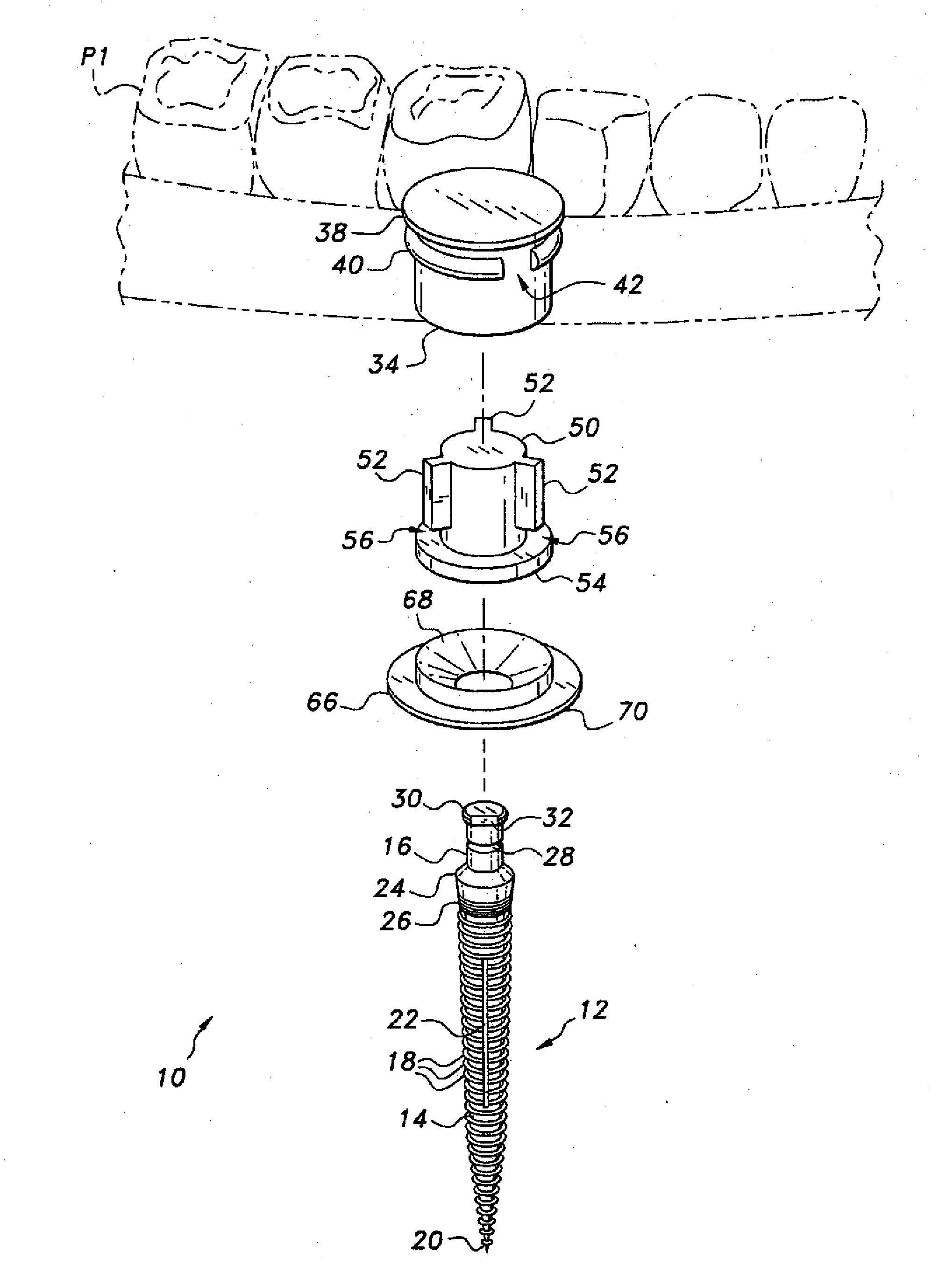
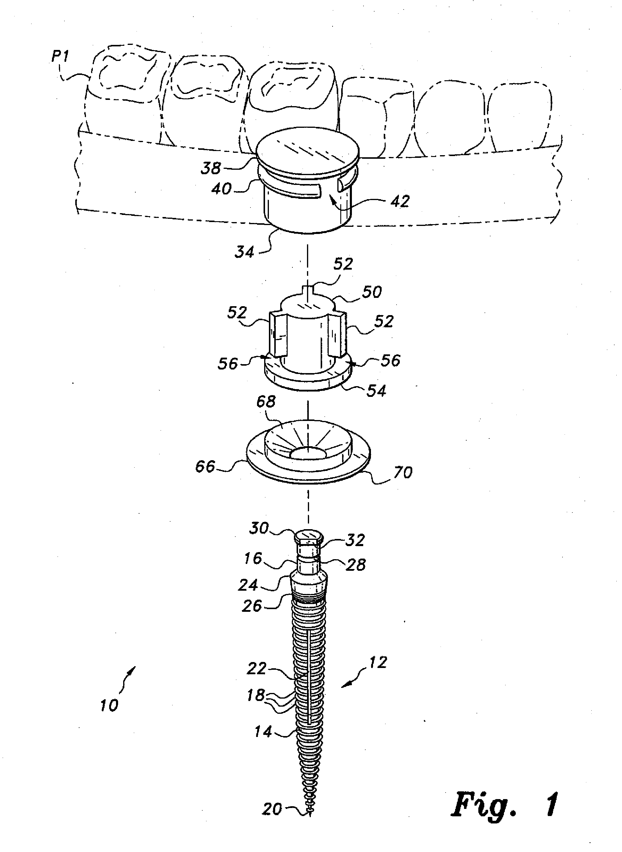
[0026]The present invention relates to a dental implant system incorporating mini dental implants having abutments formed integrally therewith. The system includes implant embodiments for installing both removable and fixed dental prostheses, as well as components for use with transfer and lab processing copings and an analog and pin with a locking feature for use during the manufacture of the prosthesis. The various components of each embodiment may be provided as a kit, if so desired.

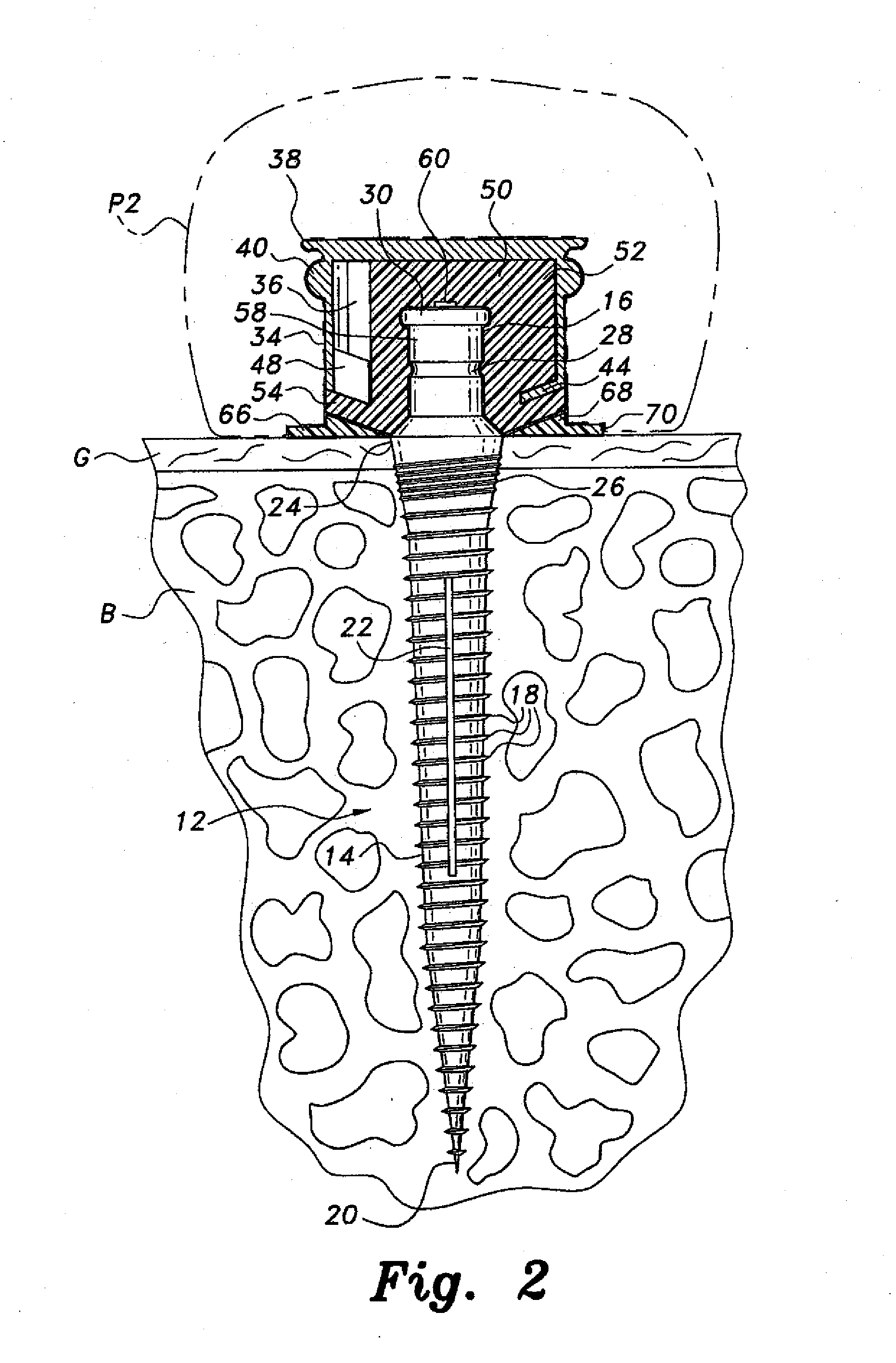
[0027]FIGS. 1 through 3 of the drawings illustrate the components and exemplary installation of a first embodiment of the dental implant system, comprising an assembly wherein the dental prosthesis is removably secured within the mouth of the user. FIG. 1 of the drawings provides a perspective view of a kit 10 for the installation of a removable prosthesis in the mouth, with FIG. 2 providing an elevation view in section of the completed installation and FIG. 3 illustrating the assembly of certain comp...


PUM


Abstract

The dental implant system includes implants having integral abutments therewith for the removable or fixed attachment of plural or single prosthetic teeth, as appropriate. The system for removable dental prostheses includes a metal housing permanently installed in the removable prosthesis, and a rubber retentive insert installed in the housing. The insert is removably installed over the abutment of the implant to secure the dental prosthesis thereto. The system includes transfer copings for transferring an impression to the lab for manufacture of the prosthesis, and lab processing copings and analogs for handling and forming the prosthesis during manufacture. The system may be assembled as a kit having some or all of the above components.

Description

CROSS-REFERENCE TO RELATED APPLICATIONS[0001]This application is a division of Ser. No. 12 / 461,954, filed on Aug. 28, 2009, now pending, which application claims the benefit of U.S. Provisional Patent Application Ser. No. 61 / 111,941, filed on Nov. 6, 2008, and Ser. No. 61 / 215,954, filed on May 12, 2009.BACKGROUND OF THE INVENTION[0002]1. Field of the Invention[0003]The present invention relates generally to the field of dentistry, and particularly to a dental implant system for mini dental implants.[0004]2. Description of the Related Art[0005]Traditional removable partial dentures, i.e., the replacement of a relatively few missing teeth with prosthetic teeth, have been secured in the mouth by means of relatively rigid wire or other metal attachments extending from the dentures and removably attached to adjacent teeth. Removable full dentures, which replace all or nearly all of the mandibular or maxillary teeth, have traditionally been adhesively secured in the mouth. Single prosthet...

Claims


Application Information

Patent Timeline
26 Sep 2013
Publication
US20130252205A1
IPC
A61C8/00
CPC
A61C8/0001; A61C8/0022; A61C8/0025; A61C8/0075; A61C8/0089; A61C8/0048
Inventors
WORTHINGTON, WILLIAM B.