Hydro electric energy generation and storage structure

a technology of hydroelectric energy and storage structure, which is applied in the direction of conventional hydroenergy generation, dynamo-electric machines, electrical apparatus, etc., can solve the problems of complex grid optimization, significant negative environmental impact on the affected area, and significant negative environmental impact of the made reservoir. achieve the effect of high power demand, low power demand, and high power demand

Active Publication Date: 2013-10-03
LEGACY MARK ROBERT JOHN
View PDF34 Cites 10 Cited by
  • Summary
  • Abstract
  • Description
  • Claims
  • Application Information

AI Technical Summary

Benefits of technology

[0009]According to another embodiment of the present invention, a hydro electric energy generation structure as described is provided, wherein the structure additionally comprises a support structure. In such an embodiment, the support structure is structurally secured to the gravity wall and adapted to support the at least one upper water storage reservoir.
[0010]According to a further embodiment of the present invention, a method of generating electrical power using the hydro electric energy generation structure described above is provided. In such an embodiment, the method of generating electrical power comprises: generating electrical power by admitting water into said at least one water inlet to power said at least one first turbine generator during a fi

Problems solved by technology

However, such known hydro electric dam applications typically require the flooding of large areas of land in order to create a sufficiently large reservoir behind a dam in order to be effective for generating electrical power, and such man-made reservoirs may have significant negative impacts on environmental characteristics of the surrounding area due to the required flooding of the reservoir, as well as the hydrological changes imposed on the areas upstream and downstream of the hydroelectric dam such as water flow changes due to the restricted and variable water flow released from the dam during power generation.
However, such pumped storage systems typically also require the construction of a dam and flooding of a land area to create one or more man-made reservoirs, which may have a significant negative environmental impact on the affect

Method used


Image

  • Hydro electric energy generation and storage structure
  • Hydro electric energy generation and storage structure
  • Hydro electric energy generation and storage structure

Examples


Embodiment Construction

[0021]Exemplary embodiments of the present invention are described below with reference to the Figures of the drawings. It is intended that the embodiments and Figures disclosed herein are to be considered illustrative rather than restrictive.

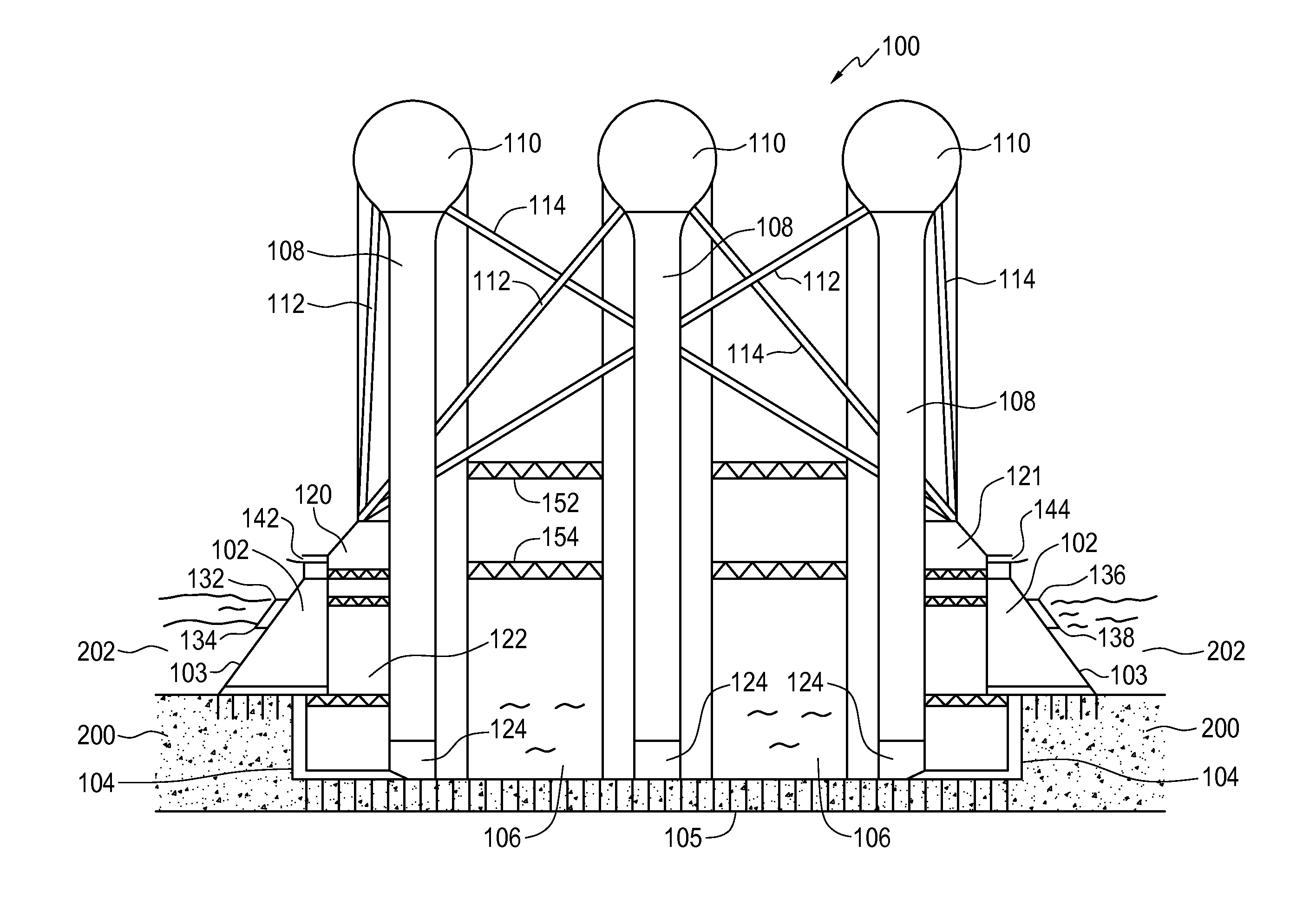
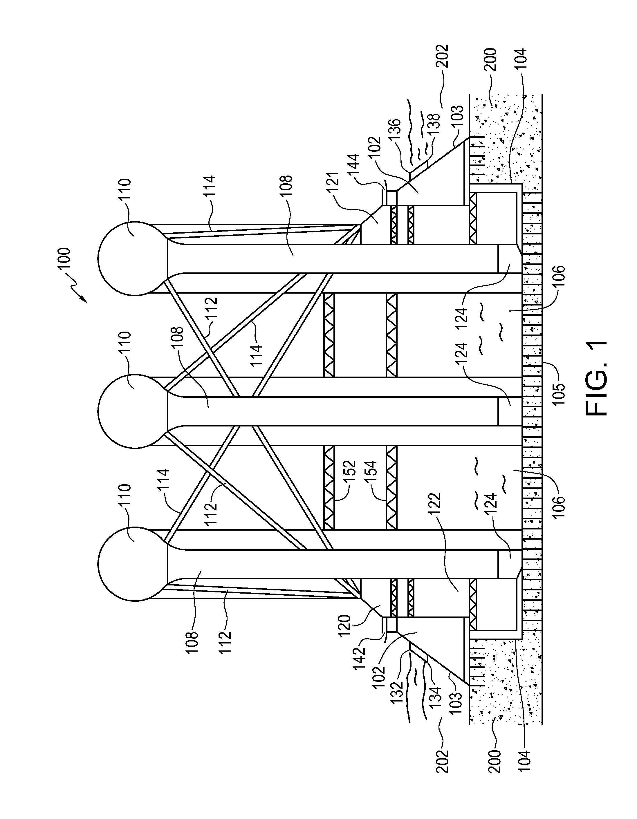
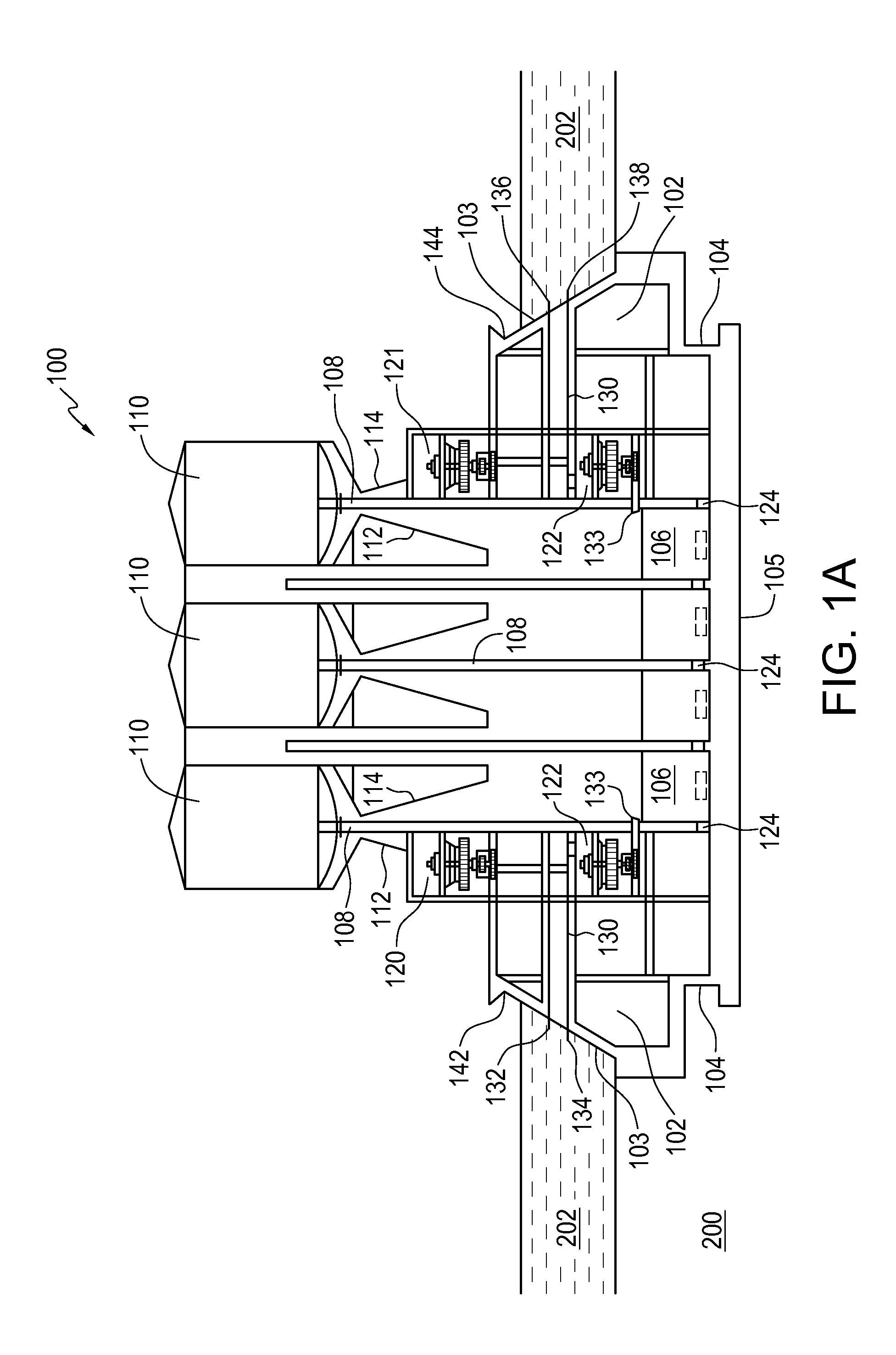
[0022]Referring now to FIGS. 1 and 1A, FIG. 1 illustrates an elevation view of an exemplary hydro electric energy generation structure 100 according to an embodiment of the present invention, and FIG. 1A illustrates an alternate cross-sectional elevation view of an exemplary hydro electric energy generation structure 100 oriented in the same direction as FIG. 1, according to an embodiment of the present invention. The exemplary hydro electric energy generation structure 100 illustrated in FIG. 1 is particularly adapted for location and installation at a site within, or adjacent to and at least partially within an existing hydraulic reservoir 202, such as an ocean (typically in a near shore marine location), a lake, an inland sea, an artificial ...


PUM


Abstract

A hydro electric energy generation structure is disclosed. The structure comprises: a gravity wall forming a closed outer perimeter extending above an upper water level of an existing hydraulic reservoir, and extending below the reservoir floor; at least one water inlet hydraulically connecting a first penstock to a first turbine generator below the water inlet. The structure further comprises: at least one lower water storage reservoir within the perimeter of the gravity wall receiving water from the first turbine generator; at least one pump receiving water from the lower water storage reservoir and pumping it through a pump delivery conduit to at least one upper water storage reservoir above the gravity wall; at least one second penstock delivering water from the upper water storage reservoir to a second turbine generator below; and a tailrace for returning the water into the existing reservoir.

Description

1. TECHNICAL FIELD[0001]The present invention relates generally to structures for generating and storing electrical energy. More particularly, the present invention relates to a structure for generating and / or storing hydro electric energy or power using an existing hydraulic reservoir.2. BACKGROUND OF THE INVENTION[0002]In the pursuit of economic and environmentally responsible or “green” electrical power generation, a variety of technology and associated systems utilizing moving water as a source of energy for generating electrical power have been developed and are typically referred to as hydro electric power generation technologies and systems according to the art. In early examples of hydro electric power utilization, water wheels were used to capture the movement of running water in rivers or streams and to power rotating electrical generators to generate electrical power.[0003]In more recent applications known in the art, hydro electric power generation systems have implement...

Claims


Application Information

Patent Timeline
IPC IPC(8): F03B13/08
CPCF03B13/08Y02E60/17Y02E10/22F03B13/06Y02E10/20Y02E60/16
Inventor LEGACY, MARK ROBERT JOHN
Owner LEGACY MARK ROBERT JOHN
Why Eureka
Try Eureka