Grinder pump basin system

a technology of grinding pump and basin system, which is applied in the direction of machines/engines, liquid fuel engines, gas current separation, etc., can solve the problems of clogging of these systems, affecting the operation of the grinding pump, and failing to address clogging issues, etc., to achieve effective and efficient cutting up solids

a technology of grinding pump and basin system, which is applied in the direction of machines/engines, liquid fuel engines, gas current separation, etc., can solve the problems of clogging of these systems, affecting the operation of the grinding pump, and failing to address clogging issues, etc., to achieve effective and efficient cutting up solids

US20130270375A1Active Publication Date: 2013-10-17ZOELLER PUMP

Image

  • Grinder pump basin system
  • Grinder pump basin system
  • Grinder pump basin system

Examples


Embodiment Construction

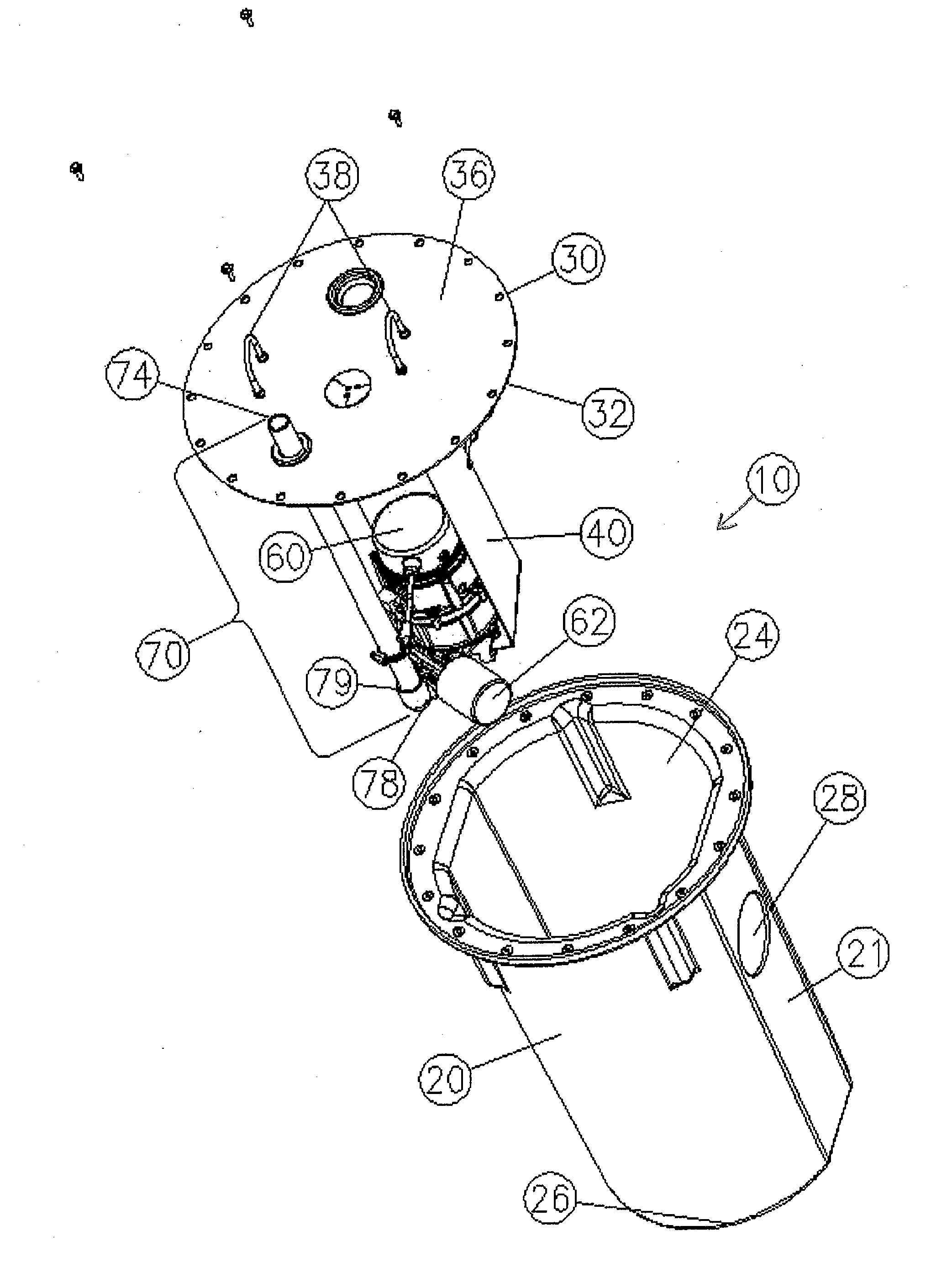
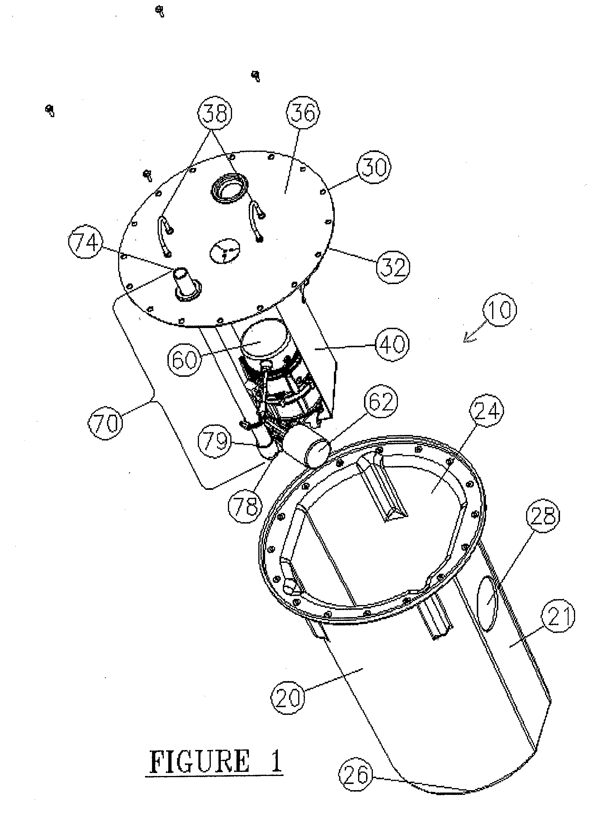
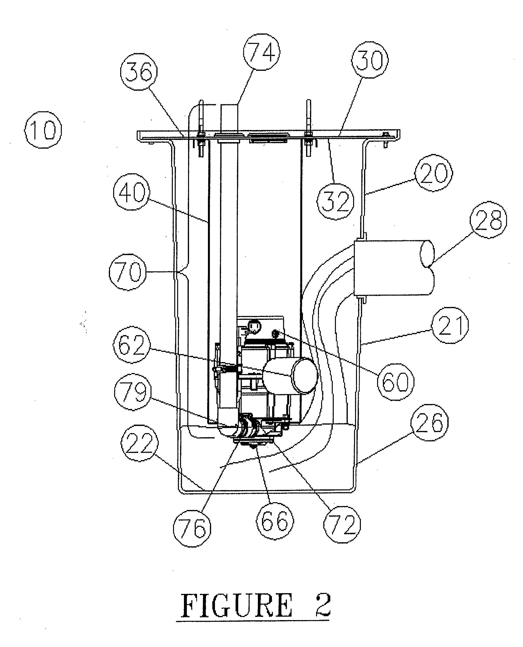
[0033]Referring to the FIGS. 1 and 2, there is shown a grinder pump basin system (10) which includes a basin (20) with a cover plate (30) securing an open, upper portion of the basin, a bracket (40) secured to the cover plate, a grinder pump (60) secured to and through the bracket, and a discharge system (70) secured to the grinder pump, which discharges waste water and ground up solids through the cover plate after treatment.

[0034]In one embodiment, the basin (20) is a conventional, tube-shaped structure with an open top (24) and a bottom inside surface (22) of a closed bottom portion (26) of the basin. The sides (21) of the basin include an inlet opening (28) for introduction of waste water and solids into the basin. (See FIG. 2.) The basin can be constructed of conventional materials, such as polypropylene. Various diameters of these basins are conventionally used including diameters of about 18 inches (46 cm) and 24 inches (61 cm).

[0035]The cover plate (30) is constructed of con...


PUM


Abstract

A grinder pump basin system is provided which includes a basin; a cover plate; a bracket secured to the cover plate; and a grinder pump with cutter plate with openings and a cutter blade secured to the bracket above a bottom surface of the basin. The openings in the cutter plate have an unique shape which assists in the cutting of material which flows through an inlet of a grinder pump. The shape of the cutter blade cooperates with the openings in the cutter plate such that solids are forced between these respective components and thereby are efficiently cut into small pieces for passing through the openings and for discharge from the grinder pump basin system.

Description

RELATED APPLICATIONS[0001]This Application is a divisional application of application Ser. No. 13 / 326,759 filed on Dec. 15, 2011, which application is continuation-in-part application claiming priority from application Ser. No. 12 / 749,153, filed Mar. 29, 2010, now abandoned, which claimed priority from provisional Application No. 61 / 219,657, filed Jun. 23, 2009 and application Ser. No. 12 / 749,134, filed Mar. 29, 2010, which also claimed priority from provisional Application No. 61 / 219,657, filed Jun. 23, 2009.FIELD OF INVENTION[0002]This invention relates to basin systems which hold pumps, particularly grinder pumps and the design of the cutting system of the grinder pumps. More particularly, this invention relates to a grinder pump basin system, wherein the grinder pump is secured to a bracket within a basin, wherein the grinder pump is not attached directly to a cover plate of the basin and wherein the grinder pump is located at a position above a bottom surface of the basin and t...

Claims


Application Information

Patent Timeline
17 Oct 2013
Publication
US20130270375A1
IPC
B02C18/00
CPC
B02C18/0092; E03F5/22; F04D7/045; F04D29/2288
Inventors
SCHMIDT, WILLIAM L.; GILBERT, DAVID R.