Electronic Cigarette and Inhaling Shell Thereof

a technology of electronic cigarettes and inhaling shells, which is applied in the direction of inhalators, tobacco, other medical devices, etc., to achieve the effects of improving the performance of guiding and sealing tobacco liquid, convenient disassembly and assembly, and facilitating maintenance and replacemen

Inactive Publication Date: 2013-12-05
HUIZHOU KIMREE TECH
View PDF8 Cites 207 Cited by
  • Summary
  • Abstract
  • Description
  • Claims
  • Application Information

AI Technical Summary

Benefits of technology

[0004]A main object of the present invention is to provide an inhaling shell of an electronic cigarette, which is convenient for disassembly and assembly, maintenance, and replacement of an atomizing device; and is convenient to repeatedly add tobacco liquid into an atomizing cup thereof, simplifies manufacturing of the inhaling shell, improves performances of guiding and sealing tobacco liquid, facilitates assembly and use of the inhaling shell, supplies an air-puffing passage ensuring the inhaling shell more compact; and has good heat insulation; and in which tobacco liquid amount is observable.

Problems solved by technology

The inhaling shell of the existing electronic cigarette has such disadvantages that: the atomizing device is single use only and it is inconvenient to repeatedly add tobacco liquid into the tobacco-liquid cup; the atomizing device and the tobacco-liquid cup are fixed in the inhaling tube and non-replaceable; the electric heat wire of the atomizing device is connected to electric circuit by wire-bond process or copper-tube riveting process, which process is very complicated and inconvenient for installation; additionally, liquid-guide tube extends into the tobacco-liquid cup, which is complicated and inconvenient for installation, and results in fluid leaking and bad results of guiding tobacco liquid; moreover, the air-puffing passage is configured and integrated in the inhaling tube, it is necessary to specially preset space for the air-puffing passage, and thus results in an incompact inner structure or a bigger dimension of the inhaling tube; and for the opaque inhaling tube, tobacco-liquid volume in the tobacco-liquid cup is unobservable, thus unfavorable-smell gas generated from burning electric heat wire will be inhaled after the tobacco liquid is exhausted.

Method used


Image

  • Electronic Cigarette and Inhaling Shell Thereof
  • Electronic Cigarette and Inhaling Shell Thereof
  • Electronic Cigarette and Inhaling Shell Thereof

Examples


Embodiment Construction

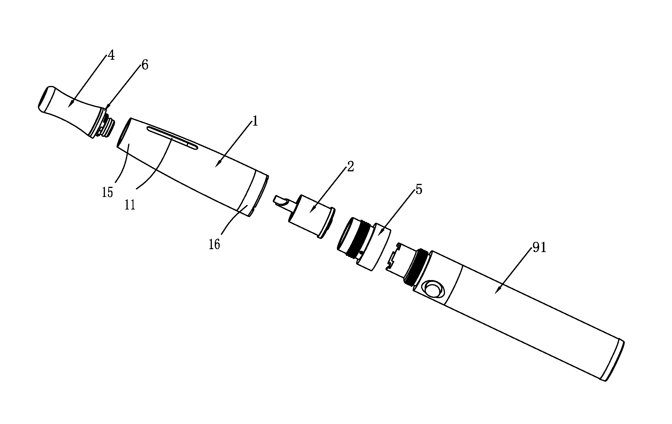
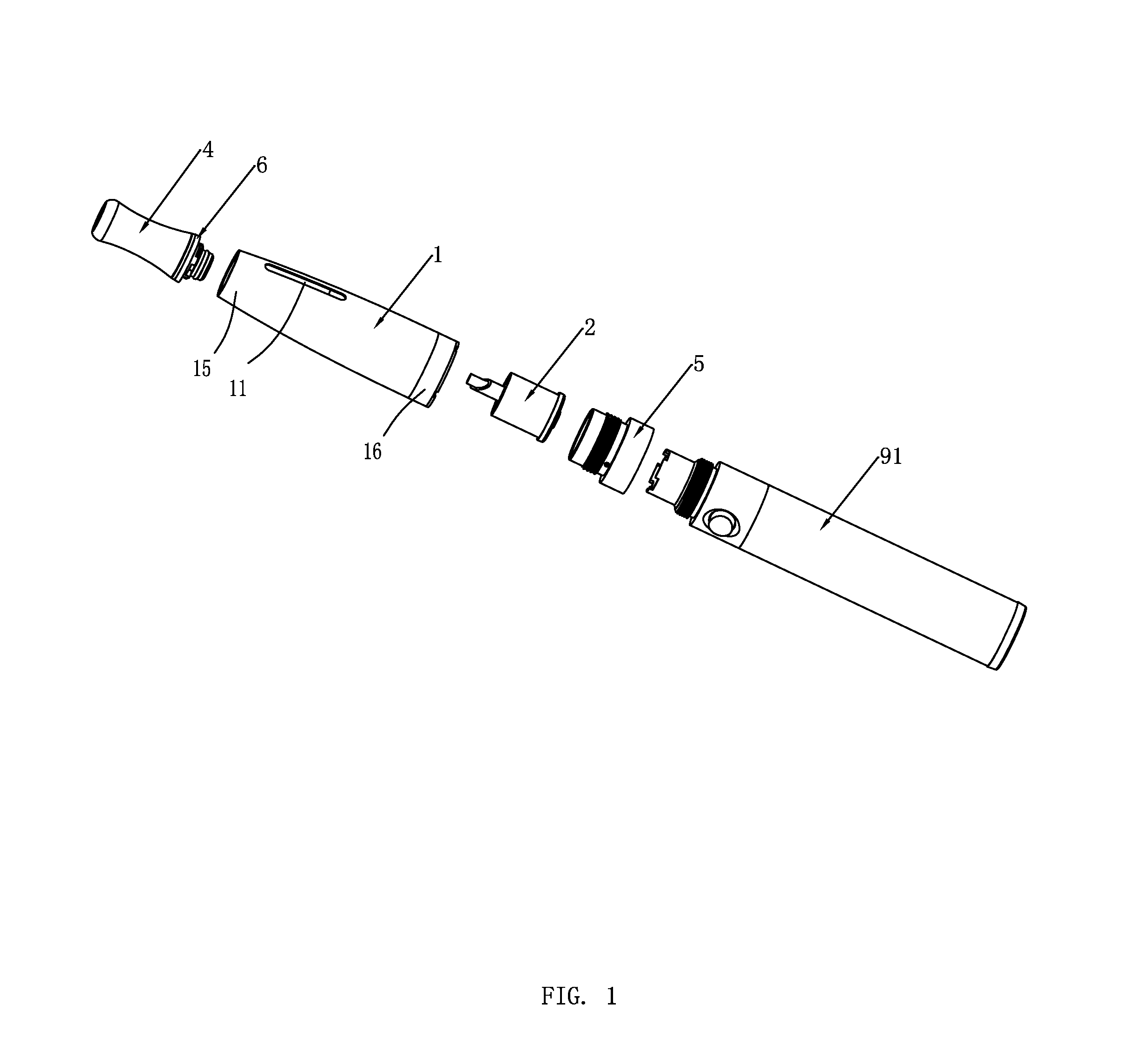
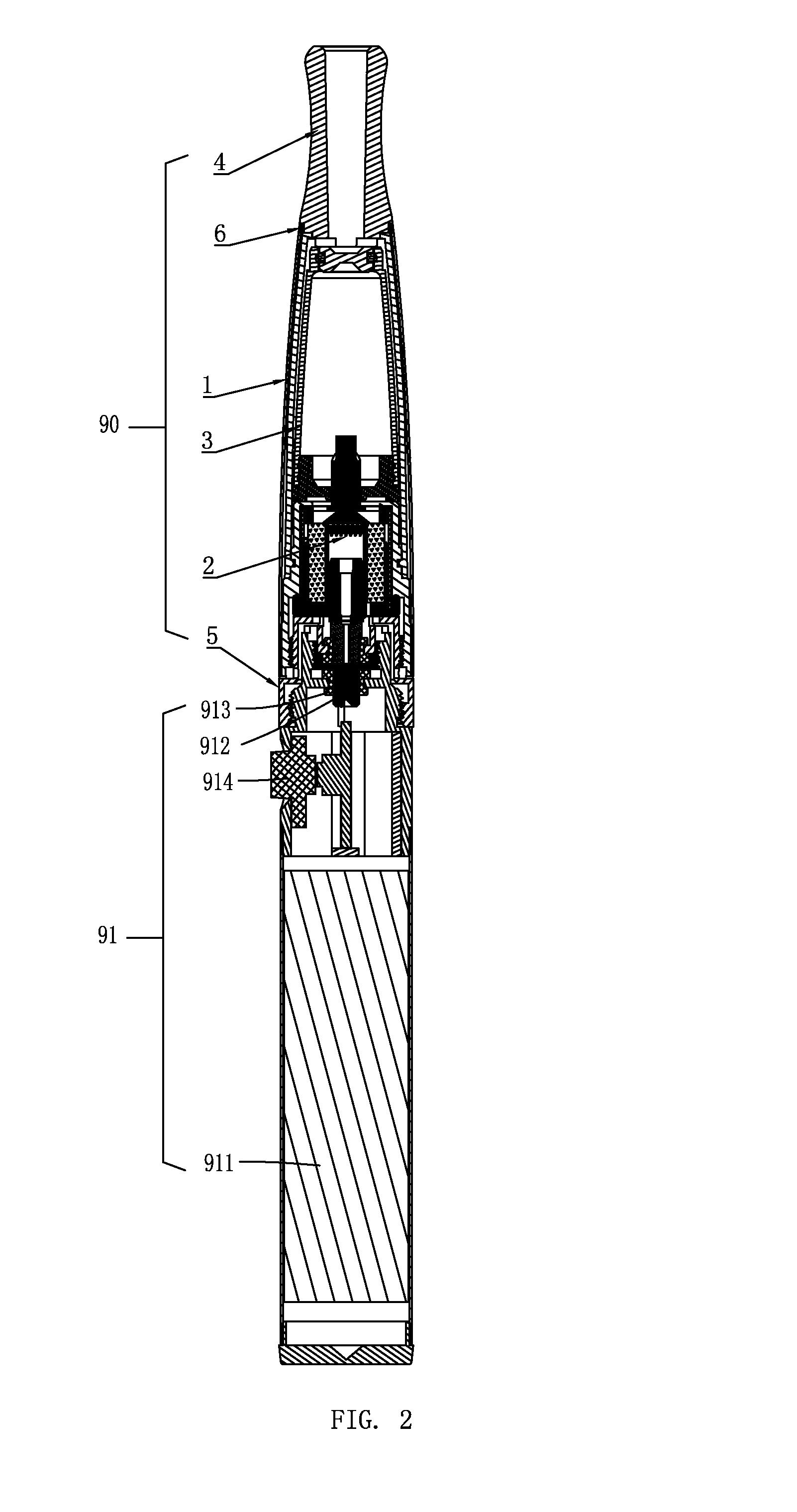
[0041]As shown in FIG. 1 to FIG. 13, a first embodiment of the present invention provides an electronic cigarette. The electronic cigarette comprises an inhaling shell 90 and a power shell 91. Herein a connecting means between the inhaling shell 90 and the power shell 91 of the electronic cigarette maybe fitting connection, plug connection, or threaded connection. The threaded connection is used in this embodiment.

[0042]As shown in FIG. 3-4, the inhaling shell 90 comprises an inhaling tube 1, an atomizing device 2, a tobacco-liquid cup 3, a mouthpiece 4, a joint member 5, and an air-puffing passage 7. The inhaling tube 1 therein is installed with the tobacco-liquid cup 3 for containing tobacco liquid, and the atomizing device 2 adjacent to the tobacco-liquid cup 3 for vaporizing tobacco liquid into aerosol. One end of the inhaling tube 1 is set with the mouthpiece 4, and the other end is set with the joint member 5 for connecting with the power shell 91. The atomizing device 2 is mo...


PUM


Abstract

An electronic cigarette and an inhaling shell are disclosed. A mouthpiece is disposed at one end of an inhaling tube, a tobacco-liquid cup and atomizing device are disposed in the inhaling tube. The atomizing device includes an atomizing cup and an atomizer. The atomizer includes an electric heat wire and a fiber piece. The atomizing cup includes a cup seat, a cup cylinder, a support tube fixed on the cup seat and a liquid-storage member fitted around the support tube. The fiber piece is fixed on the support tube with both ends against an inner wall of the liquid-storage member to absorb tobacco liquid for atomization. The electronic cigarette and the atomizing device of the present invention facilitate disassembly and assembly, maintenance, and replacement, facilitate repeatedly adding tobacco liquid into the tobacco-liquid cup, and simplify manufacturing the electronic cigarette. The configuration of an air-puffing passage thereof makes the inhaling shell more compact with good performance of guiding tobacco liquid, leakage proof tobacco liquid and a heat insulation. The tobacco liquid volume therein is observable.

Description

FIELD OF THE INVENTION[0001]The present invention relates to an electronic cigarette, and especially to an electronic cigarette and an inhaling shell thereof which can be repeatedly added with tobacco liquid repeatedly and can be replaced with an atomizing device thereof.BACKGROUND OF THE INVENTION[0002]An inhaling shell of an existing electronic cigarette includes a non-transparent inhaling tube, an atomizing device disposed in the inhaling tube which includes electric heat wire and atomizing cup, a tobacco-liquid cup disposed in the inhaling tube for storing tobacco liquid, an elongated liquid-guide tube for guiding tobacco liquid to flow into the atomizing device, a mouthpiece disposed at one end of the inhaling tube, an air-puffing passage for transporting aerosol to outside of the inhaling tube which is generated from tobacco-liquid vaporization by atomizing device. The air-puffing passage is configured in the inhaling tube and molded with the inhaling tube by an integrated mol...

Claims


Application Information

Patent Timeline
Patent Type & Authority Applications(United States)
IPC IPC(8): A61M15/06A24F15/015A24F40/10A24F40/42A24F40/44A24F40/485
CPCA61M15/06A61M11/041A61M2205/3653A61M2205/8206A61M11/042A61M11/044A24F40/10A24F40/44A24F15/015A24F40/42A24F40/485
Inventor LIU, QIUMING
Owner HUIZHOU KIMREE TECH
Why Eureka
Try Eureka