Faucet structure having pressure balance valves

a technology of pressure balance valve and valve body, which is applied in the field of faucets, can solve the problems of increasing the complexity and difficulty of the manufacturing process, affecting the maintenance of the valve body, increasing the product cost, etc., and achieves the effects of reducing cost, simplifying the manufacturing process, and convenient maintenance or replacemen

Inactive Publication Date: 2009-08-20
GLOBE UNION INDAL
View PDF2 Cites 16 Cited by
  • Summary
  • Abstract
  • Description
  • Claims
  • Application Information

AI Technical Summary

Benefits of technology

[0014]As the pressure balance valve sets are at the opened state after being pushed by the guide portion of the control valve set, once the control valve set is detached, the pressure balance valve sets can automatically close the water entry. Therefore, the control valve set can be conveniently maintained or replaced, without necessarily turning off the tap of the water supply before detaching the control valve set.
[0015]Furthermore, the lower casing of the control valve set is manufactured into an integrated structure through plastic injection moulding, and a plurality of diversion channels communicating the water entry and the water exit with the control valve set is integrally formed within the lower casing. Therefore, the manufacturing process is simplified, the cost is reduced, and the production yield is increased.

Problems solved by technology

Therefore, the maintainers must firstly leave for the place where the tap of the water supply is installed to close the water supply, and then return to the house to drain off the water in the pipeline by opening the faucet, and then detach the body 9 for maintenance or replacement, which is tedious and causes troubles for the maintainers.
Furthermore, when manufacturing the valve seat 8, the water entries 82, 83 and the water exit 84 must be manufactured within the valve seat 8 made of metal, and the water entries 82, 83 and the water exit 84 within the valve seat 8 all have bended or even twisted configurations, so that the complexity and difficulty of the manufacturing process are thus increased, which not only increases the product cost, but also raises the defect rate of the product.

Method used


Image

  • Faucet structure having pressure balance valves
  • Faucet structure having pressure balance valves
  • Faucet structure having pressure balance valves

Examples


Embodiment Construction

[0025]Reference will now be made in detail to the present preferred embodiments of the invention, examples of which are illustrated in the accompanying drawings. Wherever possible, the same reference numbers are used in the drawings and the description to refer to the same or like parts.

[0026]Referring to FIGS. 1 to 5, they show a structure of a preferred embodiment of the present invention.

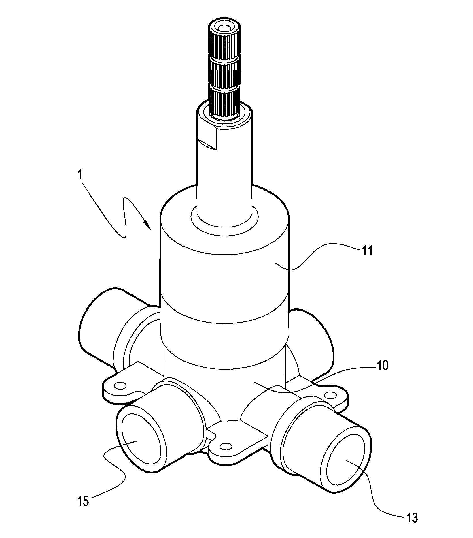
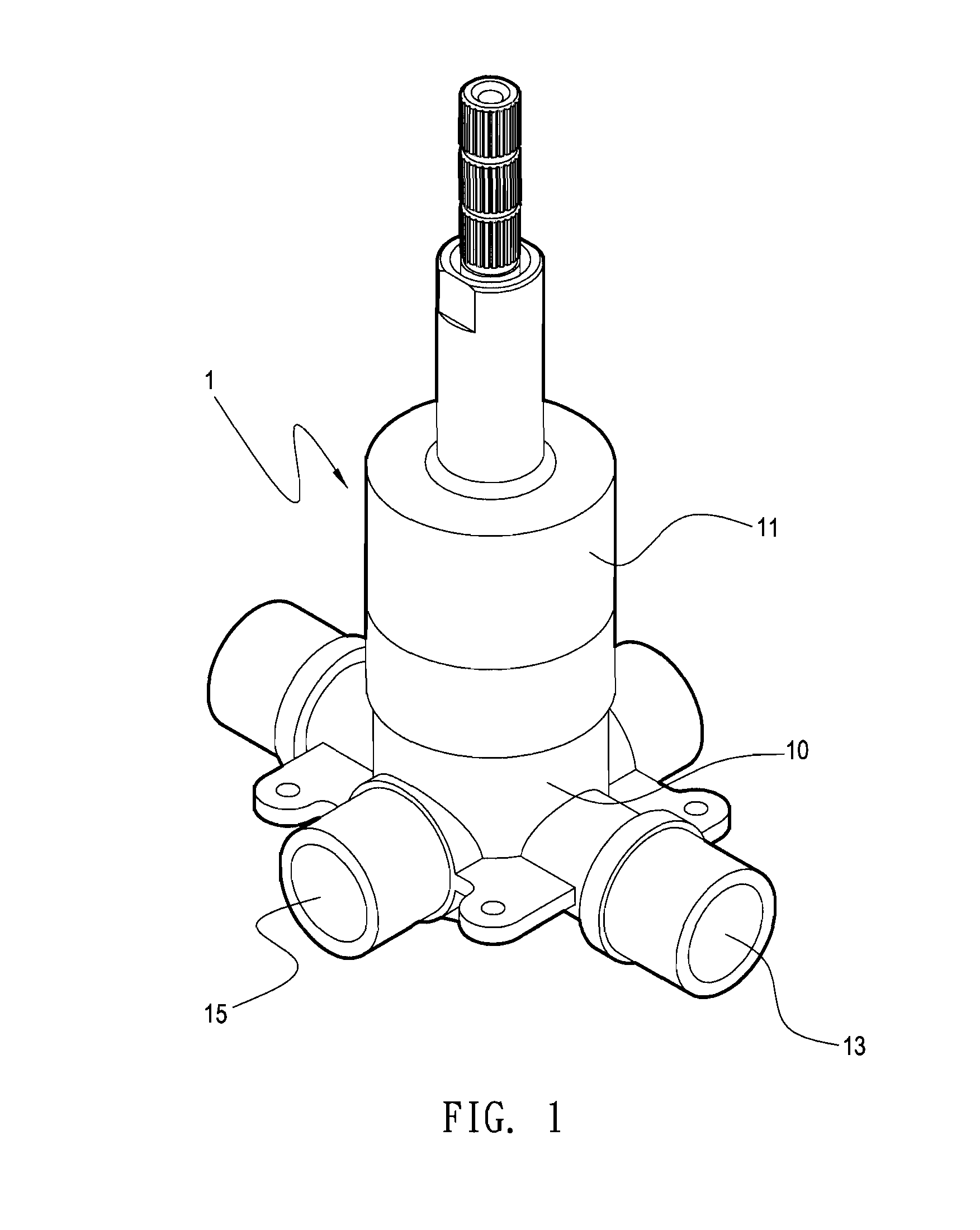
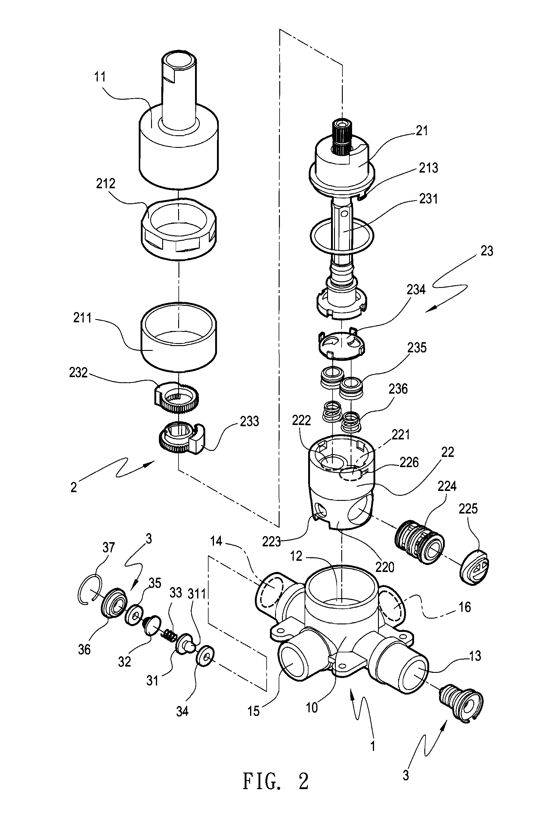
[0027]Referring to FIGS. 1 and 2, FIG. 1 is an outside view of the present invention, and FIG. 2 is an exploded perspective view of the present invention.

[0028]The faucet of the present invention includes a valve seat 1, a control valve set 2, and two pressure balance valve sets 3.

[0029]The valve seat 1 includes a seat body 10 and a cover 11, and once the seat body 10 and the cover 11 are combined together, the control valve set 2 may be disposed therein. The seat body 10 has a valve chamber 12 therein, and has two water entries 13, 14 and two water exits 15, 16 communicating with the exterior fr...


PUM


Abstract

A faucet structure having pressure balance valves includes a valve seat, a control valve set, and pressure balance valve sets. The valve seat has a valve chamber for the control valve set to be disposed therein, and has a water entry and a water exit. The pressure balance valve sets are disposed in the entry, and capable of closing the entry. A valve sheet of the pressure balance valve sets has a protrusion extending into the valve chamber, and the control valve set has a guide portion at an end extending into the valve chamber corresponding to the protrusion, such that when the control valve set is disposed in the valve chamber, the guide portion pushes against the protrusion, so as to enable the pressure balance valve sets to open the entry. When the control valve set is detached, the pressure balance valve sets are capable of closing the entry.

Description

BACKGROUND OF THE INVENTION[0001]1. Field of the Invention[0002]The present invention generally relates to a faucet, in particular, to a faucet structure having pressure balance valve sets therein and capable of automatically closing a water entry when detaching a control valve set.[0003]2. Description of Related Art[0004]Referring to FIG. 6, it shows a conventional faucet, which mainly includes a valve seat 8 and a body 9.[0005]The valve seat 8 has a valve chamber 81, and has two water entries 82, 83 and one water exit 84 disposed within the valve chamber 81. The two water entries 82, 83 extend to penetrate the valve seat 8, so as to respectively form inlet pipes 82a, 83a. The water exit 84 extends to penetrate the valve seat 8, so as to form two outlet pipes 84a, 84b that are communicated with each other.[0006]A control valve set (not shown) is disposed within the body 9, and is manipulated through a handle 91. The control valve set has water inlets 92, 93 and a water outlet 94 re...

Claims


Application Information

Patent Timeline
Patent Type & Authority Applications(United States)
IPC IPC(8): G05D11/02
CPCF16K11/0743F16K27/045F16K15/026Y10T137/2521
Inventor YUAN, CHIN-HUA
Owner GLOBE UNION INDAL
Why Eureka
Try Eureka