

Solid state thin disk laser
- Summary
- Abstract
- Description
- Claims
- Application Information
AI Technical Summary
Benefits of technology
Problems solved by technology
Method used
Image

Examples
Embodiment Construction
[0037]To further illustrate the invention, experiments detailing a laser are described below. It should be noted that the following examples are intended to describe and not to limit the invention.
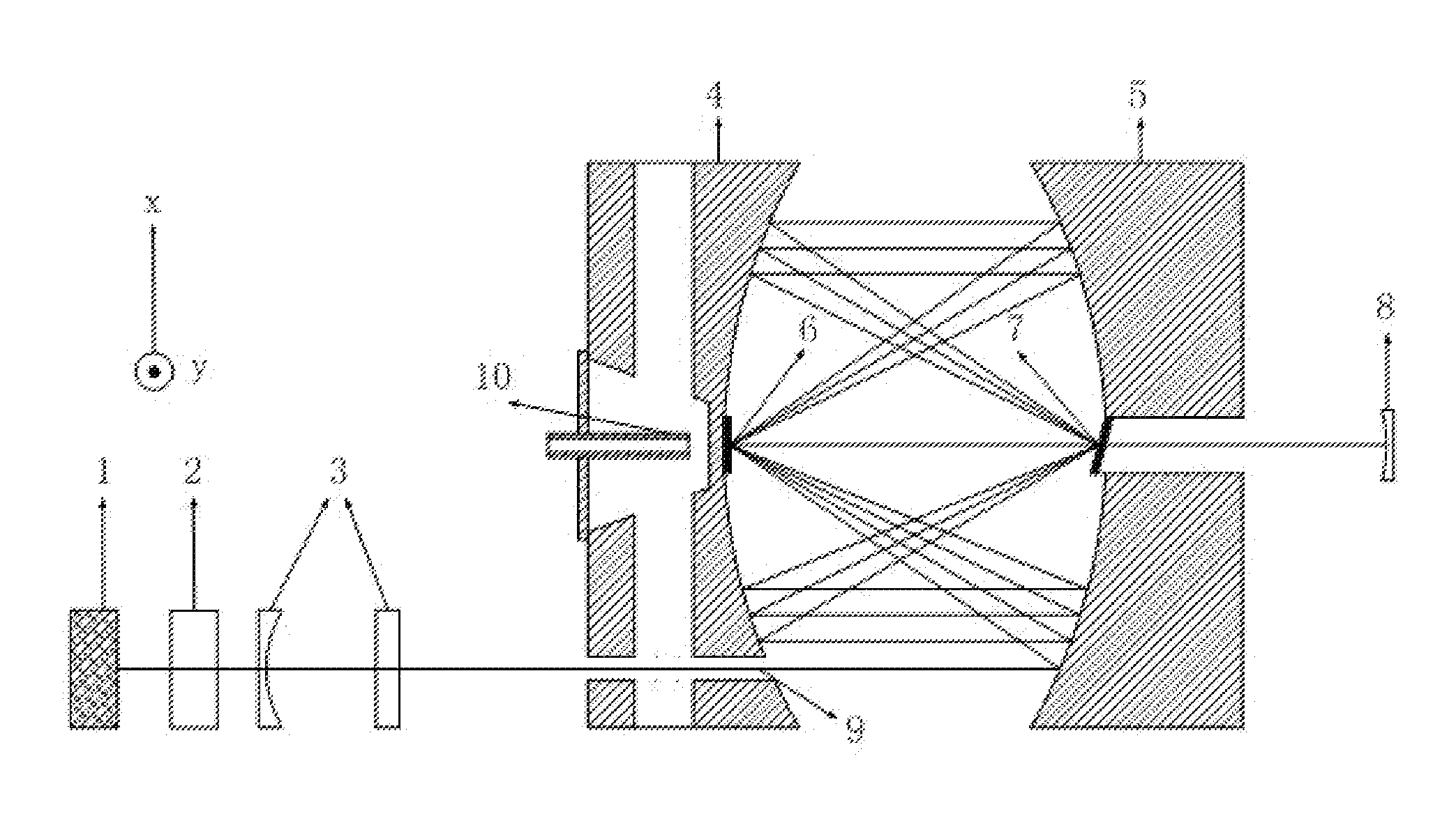
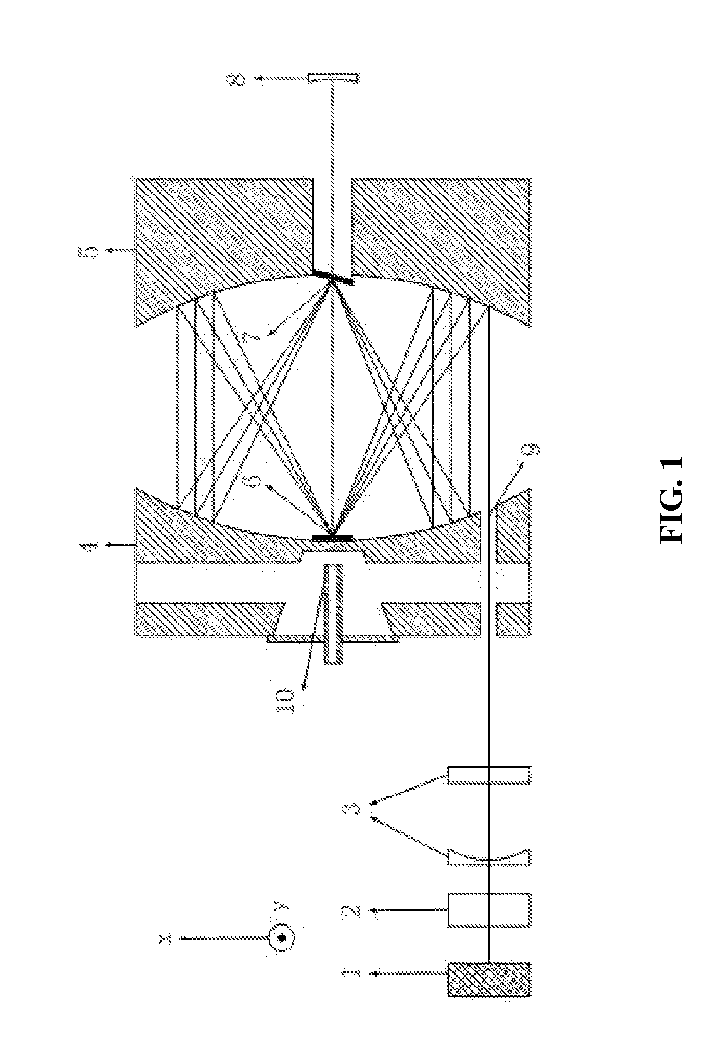
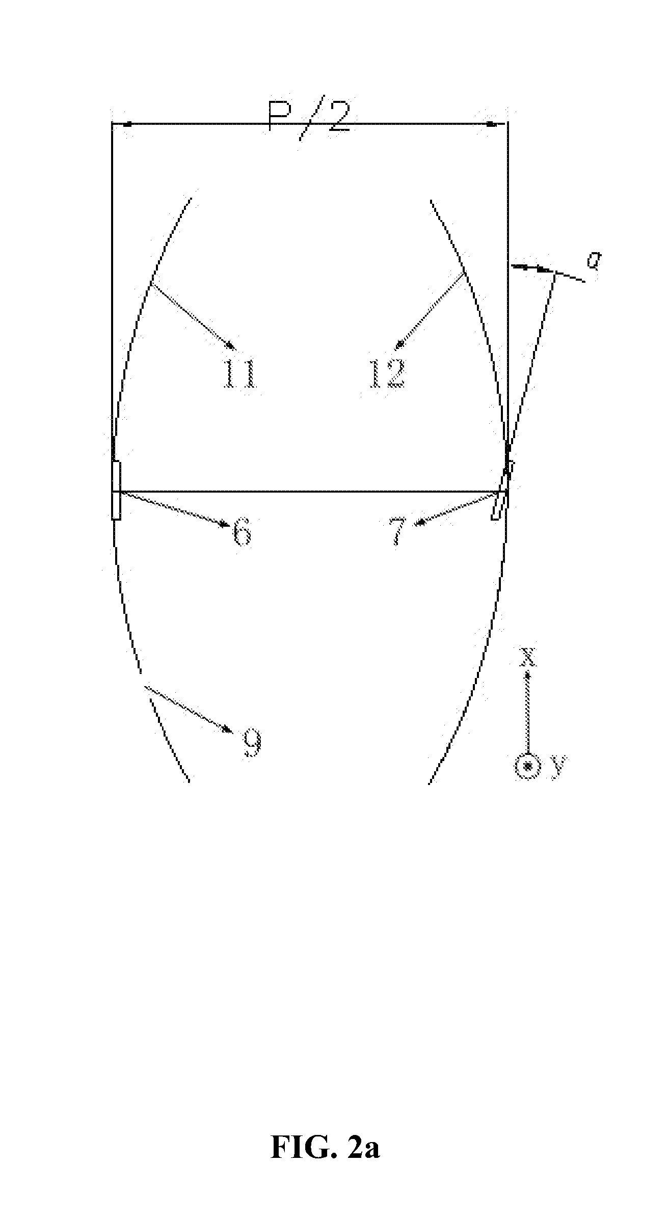
[0038]The invention adopts one or more semiconductor laser stack groups as a source of pump. Two parabolic reflectors, a thin-disk laser crystal, a corrective reflector or optical element of diffuse reflection are formed into a multi-pumping focus cavity. The collimating and focusing is performed by the two parabolic reflectors placed on conjugated axis so as to realize efficient multi-pumping pump. In the first implementation example (referred to as Example 1), some drifts exist between a bar entrance and a rapid axis of the semiconductor laser along the center of the first parabolic reflector. After being collimated, the pump light enters the focus cavity through the bar entrance. The corrective reflector with inclined position is selective in wavelength. The thin-disk crystal is install...
PUM
 Abstract
Description
Claims
Application Information