Conductive adhesive mixture, fluorescent screen anode plate and the manufacturing methods thereof

Inactive Publication Date: 2013-03-28
OCEANS KING LIGHTING SCI&TECH CO LTD
View PDF3 Cites 0 Cited by
  • Summary
  • Abstract
  • Description
  • Claims
  • Application Information

AI Technical Summary

Benefits of technology

The invention provides a conductive adhesive mixture that improves the electrical conductivity of the fluorescent screen anode plate in a simple and cost-effective way. This mixture of components helps to expand the range of application and improve the service life and light efficiency of the field emission device. The conductive adhesive mixture can also be adjusted with different components to achieve different properties, making it easier to manufacture and use. Overall, this invention simplifies the process of improving electrical conductivity and efficiency in the field emission device industry.

Problems solved by technology

The fluorescent screen anode plate generally uses the phosphor as the luminous layer; the oxide phosphor, having poor electrical conductivity, is prone to resulting in the anode charge accumulation, thus causing such problems as voltage drop, lowering the luminous efficiency of the device.

Method used


Image

  • Conductive adhesive mixture, fluorescent screen anode plate and the manufacturing methods thereof
  • Conductive adhesive mixture, fluorescent screen anode plate and the manufacturing methods thereof

Examples


example 1

[0036]Preparation of the conductive adhesive mixture: 28 g of SnCl4, 70 g of potassium silicate, 700 ml of ionized water, and 2 g of Sn nanoparticles were mixed together, and then the mixture was subjected to ultrasonic waves for 30 minutes to produce the conductive adhesive mixture.

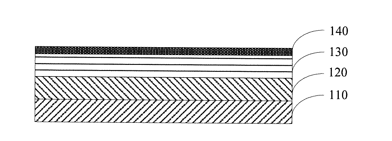
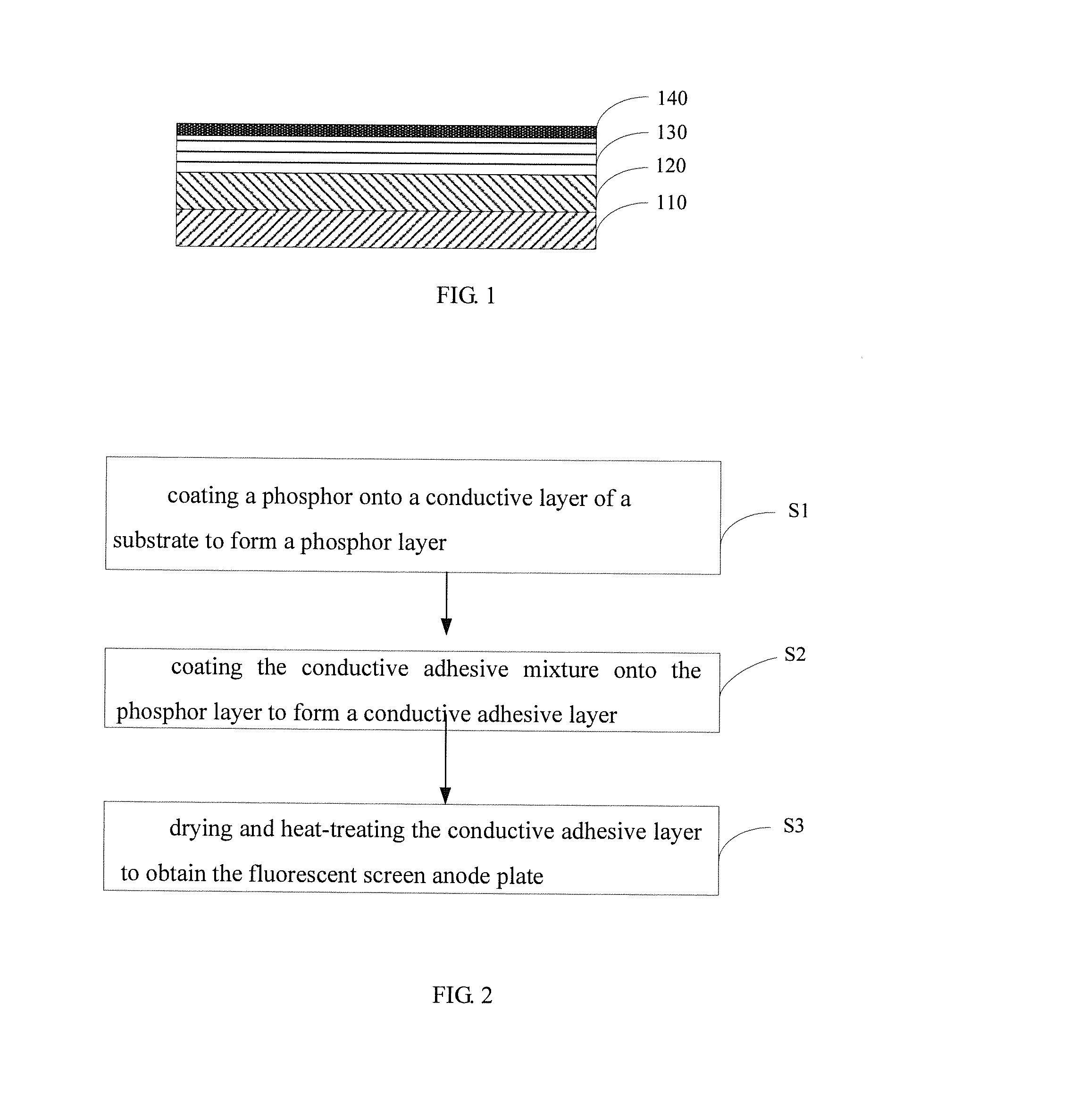
[0037]An ITO glass was cut according to a predetermined size, and then washed with acetone, alcohol and deionized water, respectively. After the ITO glass was dried, a yttrium terbium silicate green phosphor was deposited onto an ITO surface of the ITO glass to form a phosphor layer, and then the ITO glass was heat-treated at 450° C. for 30 minutes. Finally, a conductive adhesive was coated onto the surface of the phosphor layer by the spincoating process and dried at a low temperature of 45° C., and the conductive adhesive was heat treated at 120° C. for 5 hours to obtain the fluorescent screen anode plate. The conductive adhesive layer therein had a thickness of about 0.1

example 2

[0038]Preparation of the conductive adhesive mixture: 4.5 g of InCl3 solution, 95 g of sodium silicate, 600 ml of ionized water, and 0.5 g of In nanoparticles were mixed together, and then the mixture was subjected to ultrasonic waves for 30 minutes to produce the conductive adhesive mixture.

[0039]An ITO glass was cut according to a predetermined size, and then washed with acetone, alcohol and deionized water, respectively. After the ITO glass is dried, an yttrium europium oxide red phosphor was deposited onto an ITO surface of the ITO glass to form a phosphor layer, and then the ITO glass was heat-treated at 450° C. for 1 hour. Finally, a conductive adhesive was coated onto the surface of the phosphor layer by the infiltration process and dried at a low temperature of 50° C., and the conductive adhesive was heat treated at 150° C. for 2 hours to obtain the fluorescent screen anode plate. The conductive adhesive layer therein had a thickness of about 2 μm.

example 3

[0040]Preparation of the conductive adhesive mixture: 28 g of SbCl3, 72 g of poly(silicon dioxide), and 350 ml of deionized water were mixed together, and then the mixture was subjected to ultrasonic waves for 30 minutes to produce the conductive adhesive mixture.

[0041]An ITO glass was cut according to a predetermined size, and then washed with acetone, alcohol and deionized water, respectively. After the ITO glass was dried, an yttrium europium oxide red phosphor was deposited onto an ITO surface of the ITO glass to form a phosphor layer, and then the ITO glass was heat-treated at 450° C. for 2 hours. Finally, a conductive adhesive was coated onto the surface of the phosphor layer by the spincoating process and dried at a low temperature of 50° C., and the conductive adhesive was heat treated at 130° C. for 5 hours to obtain the fluorescent screen anode plate. The conductive adhesive layer therein had a thickness of about 1 μm.


PUM

PropertyMeasurementUnit
Temperatureaaaaaaaaaa

Abstract

A conductive adhesive mixture includes a component A which is 0.1% to 28% of the dry weight of the conductive adhesive mixture and a component B which is 72% to 99.9% of the dry weight of the conductive adhesive mixture. The component A is selected from one or more of the group consisting of SnCl4, InCl3 and SbCl3; and the component B is selected from one or more of the group consisting of K2O.nSiO2, Na2O.nSiO2, (SiO2)n and Al2O3. The conductive adhesive mixture, having good electrical conductivity, is used for preparation of the fluorescent screen anode plate, greatly improving the life of the luminous layer, thus improving the life and light efficiency of the field emission device. The present invention further provides a fluorescent screen anode plate manufactured with this conductive adhesive mixture and the manufacturing method thereof.

Description

FIELD OF THE INVENTION[0001]The present invention relates to vacuum microelectronics technologies, and especially to a conductive adhesive mixture, a fluorescent screen anode plate and manufacturing methods thereof.BACKGROUND OF THE INVENTION[0002]The cathodoluminescence device, particularly the field emission light source, has such advantages as energy saving, environmental protection, fast starting, being thin and light, as well as strong environmental adaptability. In the era of vigorously advocating energy saving and environmental protection, it has become an important research topic in various countries as an environmental lighting source and has huge development potential.[0003]The field emission light can be applied to the lighting source and information terminal display device. The structure of the field emission luminous device is mainly composed of a cathode electron source and an anode luminous screen. The anode luminous screen is composed of a glass substrate, a conducti...

Claims


Application Information

Patent Timeline
IPC IPC(8): H01B1/06H01B1/02B32B9/00H01B1/08
CPCH01J1/53H01J9/185H01J29/085B32B9/00Y10T428/265H01B1/06H01B1/08H01B1/16C09J9/02H01B1/02
Inventor ZHOU, MINGJIEMA, WENBOLI, QINGTAOSHAO, PENGRUI
Owner OCEANS KING LIGHTING SCI&TECH CO LTD
Why Eureka
Try Eureka