Method and Apparatus for Firetube Boiler and Ultra Low NOx Burner

a technology of nox burner and firetube boiler, which is applied in the direction of furnace-tube steam boiler, steam boiler components, flue gas purification components, etc., can solve the problems of hampered innovation in low-emission burners, inability to substantially self-control forced fgr, and complicated control, etc., to achieve low nox emissions, high thermal efficiency, and low electricity consumption

Active Publication Date: 2018-05-10
PREFERRED UTILITIES MFG
View PDF4 Cites 1 Cited by
  • Summary
  • Abstract
  • Description
  • Claims
  • Application Information

AI Technical Summary

Benefits of technology

[0012]It is a general object of the present invention to provide a method and apparatus for the production of hot water or steam in a firetube boiler and a burner system that produces low NOx emissions, low electricity consumption and high thermal efficiency.
[0013]A more specific object of the present invention is to provide a method and apparatus for the production of hot water or steam in a firetube boiler and burner system that produces ultra low NOx emissions in the flue gas, low oxygen level in the flue gas which leads to higher thermal efficiency, low horsepower requirement for the blower motor for the burner.
[0015]passing at least a portion of said first flue gas through a second pass of said boiler, wherein said second pass comprises a plurality of firetubes; routing said portion of said first flue gas to a second stage of said burner to reduce NOx emissions from said second stage of said burner; producing a second flue gas from said second stage of said burner in a third pass of said boiler; passing said second flue gas through a fourth pass of said boiler, wherein said fourth pass comprises a plurality of firetubes.
[0016]These objects are achieved by an apparatus for producing hot water or steam, comprising a firetube boiler and a burner; said firetube boiler comprising a shell substantially cylindrical in shape, having a front end and a back end; a front tube sheet and at least one back tube sheet; two furnace tubes and a plurality of firetubes positioned inside the shell and substantially extending the length of the shell from the front end to the back end, said furnace tubes form a first pass and a third pass, said firetubes form a second pass and a fourth pass in the boiler, wherein said first pass comprises a furnace tube and allows a first flue gas to be produced and flow in the direction from the front end to the back end; said second pass comprises a plurality of firetubes and allows said first flue gas to flow in the direction from the back end to the front end; said third pass comprises a furnace tube and allows a second flue gas to be produced and flow in the direction from the front end to the back end; and said fourth pass comprises a plurality of firetubes and allows said second flue gas to flow in the direction from the back end to the front end; and said burner comprising a burner affixed to the front end of said firetube boiler comprising a first stage that produces said first flue gas; a second stage that produces said second flue gas; wherein at least a portion of said first flue gas goes through said second pass of said boiler, and is routed to the second stage of the burner to reduce NOx emissions from said second flue gas; said second flue gas goes through said fourth pass of said boiler.

Problems solved by technology

However, innovations in the low emission burners have been hampered by the lack of innovations in the firetube boilers.
However it often requires a factory modified burner capable of forced FGR.
From a control standpoint, the forced FGR cannot be substantially self-controlled like induced FGR.
The addition of a separate FGR blower demands accurate and reliable control of the rate of FGR relative to the rate of combustion air, making the control more complicated.
The introduction of flue gas into the blower can sometimes lead to condensation, corrosion, and heat damage to some burner equipment.
For example, condensation on the spark ignition system could render it inoperable due to electric short-circuit.
Corrosion to the internal parts of the blower and the burner head can occur due to condensation.
Heat and condensation from the flue gas can damage or interfere with the flame scanner, which is a part of the burner management system.
The heat can also transmit through the shaft of the electric motor and damage the motor if the shaft is not properly cooled.
Induced FGR increases both the volumetric flow rate through the blower and the pressure drop through the burner and the boiler (hence increasing the blower operating pressure required), and therefore greatly increases the horsepower requirement for the blower motor.
In addition, the rapid mixing design requires large pressure drops across the swirl vanes in the combustion air pathway near the burner head.
Since mixing rate slows down with flow velocity, this design also has a limited turndown for ultra low NOx performance.
The larger motor means higher initial capital costs, higher electricity consumption and higher noise during the burner's operation.
In the state of California in particular, operators of boilers often dislike use of FGR, perhaps due to the concerns of earthquake and the additional mandatory structural inspection related to the field installation of the FGR pipe.
These premix burners have limited turndown due to flashback concerns.
The shortcomings of the “lean premixed combustion” technique are well recognized in the combustion community: low thermal efficiency due to the very high excess air level and the resultant very high oxygen level in the flue gas (9% oxygen is typical), and the extra electricity consumption due to the extra excess air for the dilution and flame cooling.
The extra dilution air carries additional heat into the atmosphere (wasted heat) when the exhaust is vented out of the stack, and causes a reduction of thermal efficiency.

Method used


Image

  • Method and Apparatus for Firetube Boiler and Ultra Low NOx Burner
  • Method and Apparatus for Firetube Boiler and Ultra Low NOx Burner
  • Method and Apparatus for Firetube Boiler and Ultra Low NOx Burner

Examples


Embodiment Construction

[0026]For the purpose of this invention, a burner shall mean a device to produce one or more flames in the firetube boiler of the current invention in a controlled manner, taking inputs from at least one fuel source and an oxidizer source such as air. The two stages of the burner disclosed in this invention could arguably be referred to as two separate burners by anyone skilled in the art. Such change of nomenclature does not create a new invention outside the scope of the current invention.

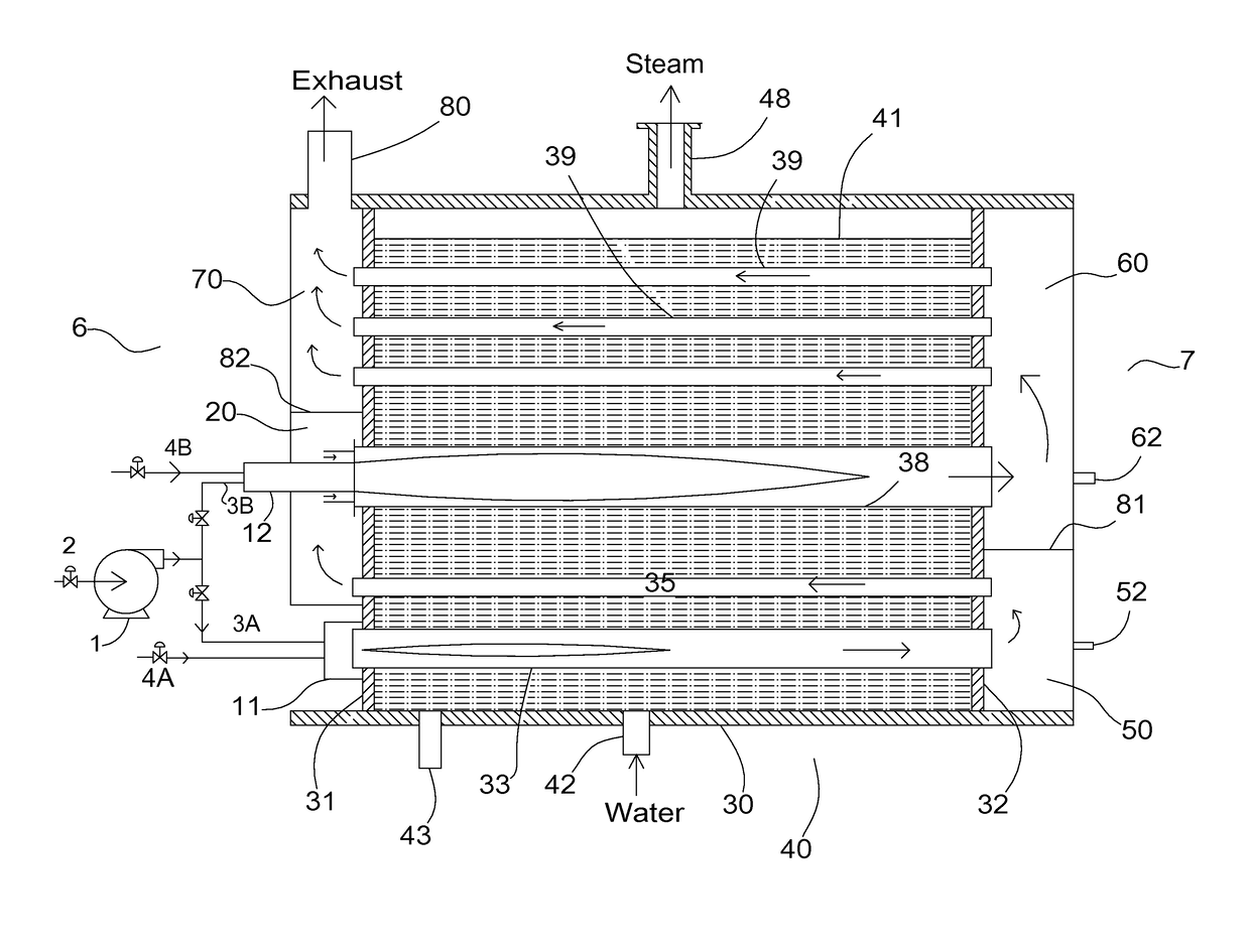
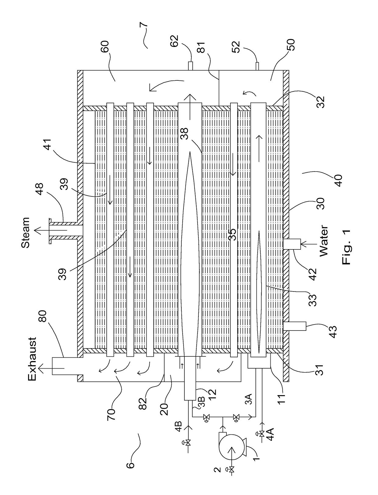
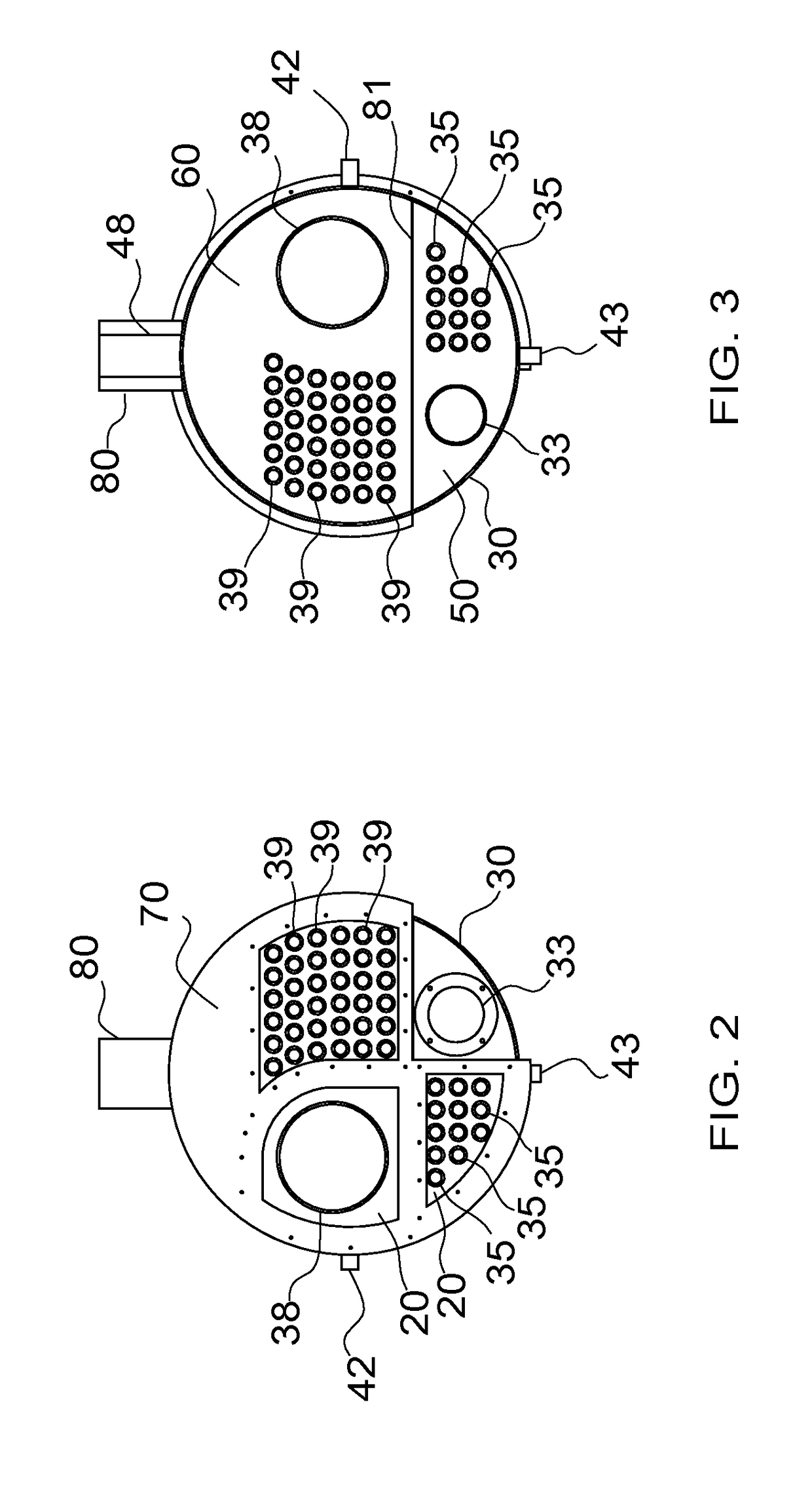
[0027]FIG. 1 shows a schematic view of an apparatus for the current invention. A boiler 5 has a cylindrical shell 30, which is welded to a front tube sheet 31 and a rear tube sheet 32 to form a pressure vessel 40. Furnace tubes 33 and 38 are positioned in the shell 30 to extend the length of the shell from tube sheet 31 and to tube sheet 32, and sealingly attached (typically welded) to these tube sheets per firetube boiler codes. A plurality of firetubes 35 and 39 are also positioned in the shell...


PUM


Abstract

The current invention disclose a method and apparatus for production of hot water or steam in a firetube boiler, said method comprising the steps of producing a first flue gas using a first stage of a burner in a first pass of a firetube boiler; passing at least a portion of said first flue gas through a second pass of said boiler, wherein said second pass comprises a plurality of firetubes; routing said portion of said first flue gas to a second stage of said burner to reduce NOx emissions from said second stage of said burner; producing a second flue gas from said second stage of said burner in a third pass of said boiler; passing said second flue gas through a fourth pass of said boiler, wherein said fourth pass comprises a plurality of firetubes.

Description

[0001]This is a continuation of application Ser. No. 14 / 941,842 filed on Nov. 16, 2015.BACKGROUND OF THE INVENTION1. Field of the Invention[0002]This invention relates generally to a firetube boiler and a burner system for the production of hot water or steam. More particularly, this invention relates to the production of hot water or steam using a firetube boiler and a burner system that are designed to produce ultra low NOx emissions and higher efficiency at the same time. The firetube boiler and the burner of this invention are specifically designed to work with each other.2. Description of the Related Art[0003]Boilers are widely used for the generation of hot water and steam. A conventional boiler (excluding Heat Recovery Steam Generator or HRSG) comprises a furnace in which fuel is burned, and surfaces typically in the form of steel tubes to transfer heat from the flue gas to the water. A conventional boiler has a furnace that burns a fossil fuel or, in some installations, wast...

Claims


Application Information

Patent Timeline
Patent Type & Authority Applications(United States)
IPC IPC(8): F22B9/00F22B37/00
CPCF22B37/008F22B9/00F22B7/12
Inventor HONG, JIANHUI
Owner PREFERRED UTILITIES MFG
Why Eureka
Try Eureka