
Method and apparatus for reducing gas turbine engine emissions

a gas turbine engine and emission reduction technology, applied in the direction of engine ignition, engine starters, lighting and heating apparatus, etc., can solve the problems of low emissions and maximum operability, long prior art can-type combustors, and nitrogen oxide formation within gas turbine engines. , to achieve the effect of reducing emissions

Inactive Publication Date: 2008-01-24
GENERAL ELECTRIC CO
View PDF31 Cites 53 Cited by
  • Summary
  • Abstract
  • Description
  • Claims
  • Application Information

AI Technical Summary

Benefits of technology

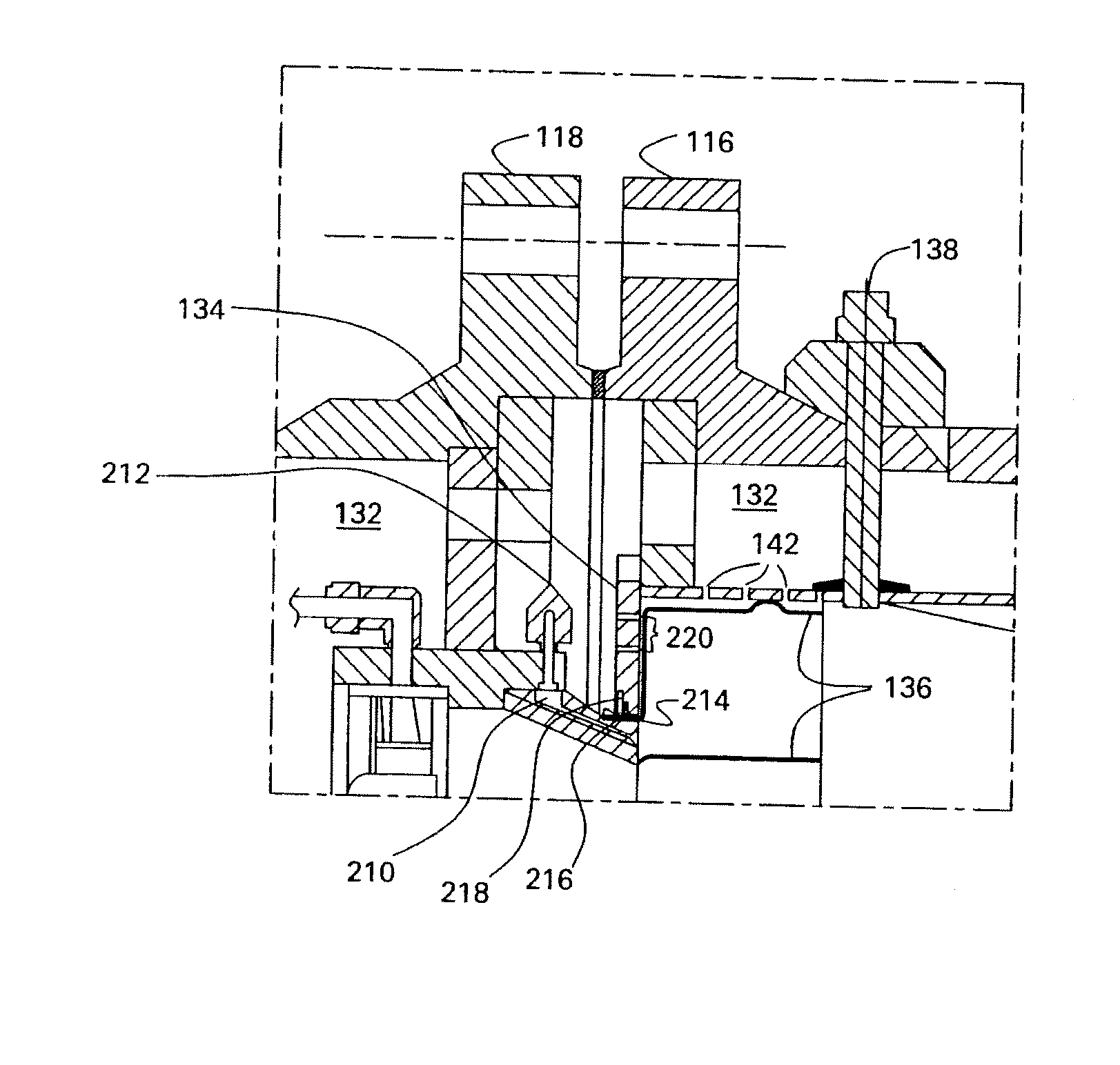
[0015] A process for reducing NOx emissions in a gas turbine employing a can-type combustor comprising a plurality of swirler and mixer assemblies comprises independently operating a primary fuel delivery system to at least one of the plurality of swirler and mixer assemblies, wherein the primary fuel delivery system injects fuel into a swirler of the at least one swirler and mixer assemblies to operate at a different fuel to air equivalence ratio than the other swirler and mixer assemblies; and operating a secondary fuel delivery system to each one of the plurality of swirler and mixer assemblies, wherein the secondary fuel delivery system injects a fuel to combustion chamber via an opening disposed in a shroud surrounding each one of the plurality of swirler and mixer assemblies.

Problems solved by technology

In particular, nitrogen oxide is formed within a gas turbine engine as a result of the high combustor flame temperatures during operation.
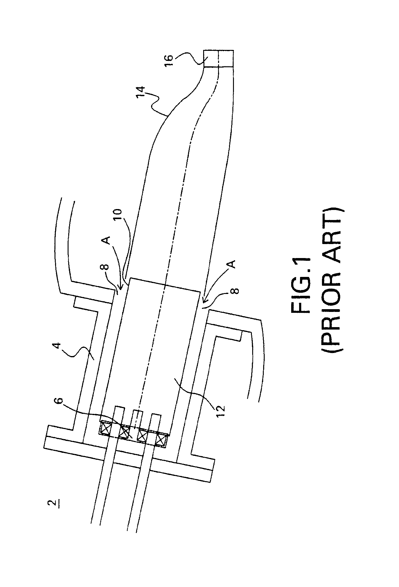
Although this system is practical and easy to assemble, prior art can-type combustors have several inherent disadvantages for achieving ultra-low emissions and maximum operability.
Prior art can-type combustors are relatively lengthy and provide a long combustor residence time.
However, during high load and / or high temperature operation, diatomic nitrogen begins to react with combustion intermediate species (O-atoms, OH, etc), and NOx emissions grow in time.
Therefore, the large residence time of the can-type combustor results in high NOx emissions during high-load and / or high temperature operation.
This results in a long combustor residence time and accordingly, during high temperature and / or high load operation, high levels of NOx emissions.
However, the can-type combustor works well during low temperature and / or low load operation, as the long combustor residence time allows the CO and UHC to burn off (i.e., oxidize more completely) during this long period, resulting in low CO and UHC emission levels.
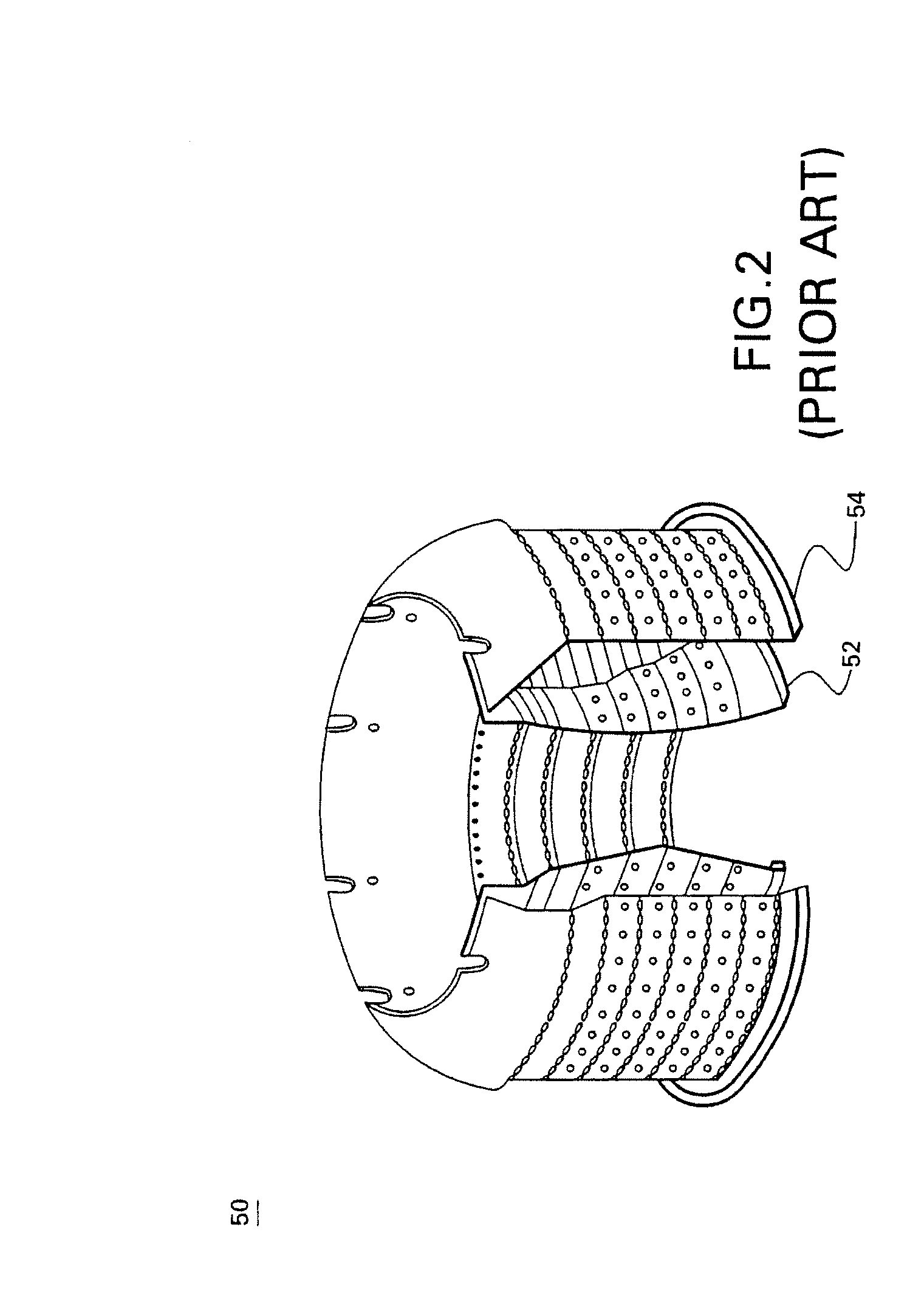
During high load and / or high temperature operation, the levels of NOx emissions are low due to the short combustor residence time in the short annular combustor.
However, during low load and / or low temperature operation, the levels of carbon monoxide (CO) and unburned hydrocarbon (UHC) are large due to the short combustor residence time of the annular-type combustor, not allowing complete CO and UHC burnout (i.e., oxidation).
The combustor residence time is low, and accordingly, during low temperature and / or low load operation, high levels of CO and UHC emissions are present.
In addition, one other important down side of annular combustors operation is the multitude of acoustic modes of the combustion system (transversal and longitudinal), which are especially prone to excitation in the case of lean premix flames, and may therefore result in high amplitude pressure fluctuations, generally at high loads.
However, the annular combustor works well during high temperature or high load operation, as the short combustor residence time does not give the NOx emissions sufficient growth time, resulting in low levels of NOx emissions.
The latter is usually employed in conditions other than the design point (full speed load), where stabilization of a premixed lean flame is generally difficult to achieve.
The result is that, in either premixer configuration (e.g., annular or can type,) higher emissions (whether it be CO and UHC as in the case of annular type combustors or NOx as in the case of can-type combustors) occur at conditions other than the design set point and that no flexibility is permitted in either premixer configuration to operate the premixers independently at different fuel rates.

Method used


Image

  • Method and apparatus for reducing gas turbine engine emissions
  • Method and apparatus for reducing gas turbine engine emissions
  • Method and apparatus for reducing gas turbine engine emissions

Examples


example 1

[0049] In this example, emissions were monitored for a turbine shown in FIG. 3 employing a can type combustor in accordance with the present disclosure. Emissions were monitored at various points across the combustor liner during operation of the microturbine at full speed and, full load (FSFL). As is graphically shown in FIG. 11, a NOx emission was less than about 3 parts per million (ppm) across the entire combustor liner. Although the residence time in the can type combustor is relatively long compared to annular type combustors, the independently operated premixers employed in the can type combustors provides a robust process with minimal NOx emissions and minimal dynamic pressure fluctuations. Levels of carbon monoxide at FSFL averaged less than about 10 ppm across the combustor liner. During low load and / or low temperature operation, the levels of carbon monoxide (CO) and unburned hydrocarbons are expected to be minimal due to the compact flame structure and long combustor res...


PUM


Abstract

A low emission turbine includes a reverse flow can-type combustor that generally includes a primary and secondary fuel delivery system that can be independently controlled to produce low CO, UHC, and NOx emissions at design set point and at conditions other than design set point. The reverse flow can-type combustor generally includes an annularly arranged array of swirler and mixer assemblies within the combustor, wherein each swirler and mixer in the array includes a primary and secondary fuel delivery system that can be independently controlled. Also disclosed herein is a can-type combustor that includes fluid passageways that perpendicularly impinge the backside of a heat shield. Processes for operating the can-type combustors are also disclosed.

Description

STATEMENT REGARDING FEDERALLY SPONSORED RESEARCH OR DEVELOPMENT [0001] This invention was made with U.S. government support under Government Contract No.: DE-FC02-OOCH11063. The U.S. government has certain rights in this invention.BACKGROUND [0002] This disclosure generally relates to gas turbine engines, and more particularly, to combustors for gas turbine engines. [0003] Microturbines are small gas turbines typically used for on-site power generation. They operate on the same principle as a jet engine but can use a variety of commercially available fuels, such as natural gas, diesel, bio-diesel, gasoline, kerosene, propane, methane, digester gas, reformed fuels, products of gasification and the like. Microturbines have the ability to operate in grid-connected, stand-alone, and dual modes. Grid-connected mode generally allows the unit to operate parallel to the grid, providing base loading and peak shaving. Stand-alone mode generally allows the units to operate completely isolated ...

Claims


Application Information

Patent Timeline
IPC IPC(8): F02C1/00
CPCF02C9/40F05D2220/75F05D2250/82F05D2270/082F23C2900/03001F23R3/14F05D2260/96F23R3/44F23R2900/00002Y02T50/675Y02T50/677Y02T50/678F23R3/286Y02T50/60
Inventor COLIBABA-EVULET, ANDREIBOWMAN, MICHAEL JOHNSANDERSON, SIMON RALPHDEAN, ANTHONY JOHN
Owner GENERAL ELECTRIC CO
Learn More