Low emission turbine system and method

a low-emission, turbine technology, applied in the direction of machines/engines, mechanical equipment, electric generator control, etc., can solve the problems of high co emissions, small operability window of such combustors, and difficulty in operating premixers employed in combustors outside of their design spa

Inactive Publication Date: 2009-09-03
GENERAL ELECTRIC CO
View PDF21 Cites 146 Cited by
  • Summary
  • Abstract
  • Description
  • Claims
  • Application Information

AI Technical Summary

Benefits of technology

[0007]Briefly, according to one embodiment, a turbine system is provided. The turbine system includes a compressor configured to compress ambient air and a combustor configured to receive compressed air from the compressor and to combust a fuel stream to generate an exhaust gas. The turbine system also includes a turbine for receiving the exhaust gas from the combustor to generate electricity; wherein a first portion of the exhaust gas is mixed with the ambient air to form a low-oxygen air stream, and wherein the low-oxygen air stream is compressed, using the compressor, and is directed to the combustor for combusting the fuel stream to generate a low-NOx exhaust gas.
[0008]Another embodiment also includes a turbine system. The turbine system includes a compressor configured to compress ambient air and at least a portion of an exhaust gas to form a compressed low-oxygen air stream. The turbine system also includes a combustor configured to receive the compressed low-oxygen air stream from the compressor, and to combust a fuel stream in a rich-quench-lean (RQL) mode of combustion, to generate the exhaust gas. The turbine system also includes a turbine for receiving the exhaust gas from the combustor to generate electricity and a low-NOx exhaust gas, wherein a first portion of the exhaust gas is recirculated to the compressor to form the low-oxygen air stream.
[0009]In another embodiment, an integrated coal gasification combined cycle (IGCC) system is provided. The IGCC system includes a gasifier configured to produce a syngas fuel from coal, and a turbine system coupled to the gasifier. The turbine system includes a compressor configured to compress ambient air and at least a portion of an exhaust gas to form a compressed low-oxygen air stream. The system further includes a combustor configured to receive the compressed low-oxygen air stream from the compressor, and to combust the syngas fuel in a rich-quench-lean (RQL) mode of combustion, to generate the exhaust gas. The turbine system also includes a turbine for receiving the exhaust gas from the combustor to generate electricity and a low-NOx exhaust gas, wherein a first portion of the exhaust gas is recirculated to the compressor to form the low-oxygen air stream.
[0010]In another embodiment, a method of operating a turbine system is provided. The method includes producing a compressed air stream, combusting the compressed air stream with a fuel stream to form an exhaust gas, and expanding the exhaust gas to generate electricity. The method also includes compressing and mixing a first portion of the exhaust gas with an air stream to form a low-oxygen air stream, and combusting the low-oxygen air stream with the fuel stream to generate a low-NOx exhaust gas.

Problems solved by technology

Further, certain gas turbine systems are utilized using high levels of airflow, thereby resulting in lean fuel mixtures with a flame temperature that is low enough to reduce the formation of NOx.
However, because lean flames have a low flame temperature, they result in high CO emissions.
Further, the window of operability becomes very small for such combustors and the combustors are required to be operated away from the lean blow out limit.
As a result, it is difficult to operate the premixers employed in the combustors outside of their design space.
Moreover, when sufficiently lean flames are subjected to power setting changes, flow disturbances, or variations in fuel composition, the resulting equivalence ratio perturbations may cause loss of combustion.
Such a blowout may cause loss of power and expensive down times in stationary turbines.
However, incorporation of additional components, such as a catalytic reactor for the SCR process, is a challenge, due to costs and the added complexity of such systems.

Method used


Image

  • Low emission turbine system and method
  • Low emission turbine system and method
  • Low emission turbine system and method

Examples


Embodiment Construction

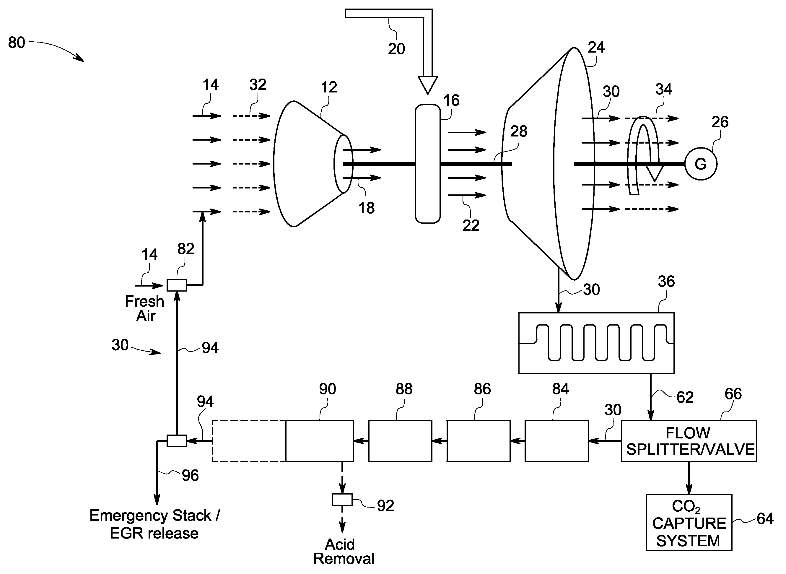
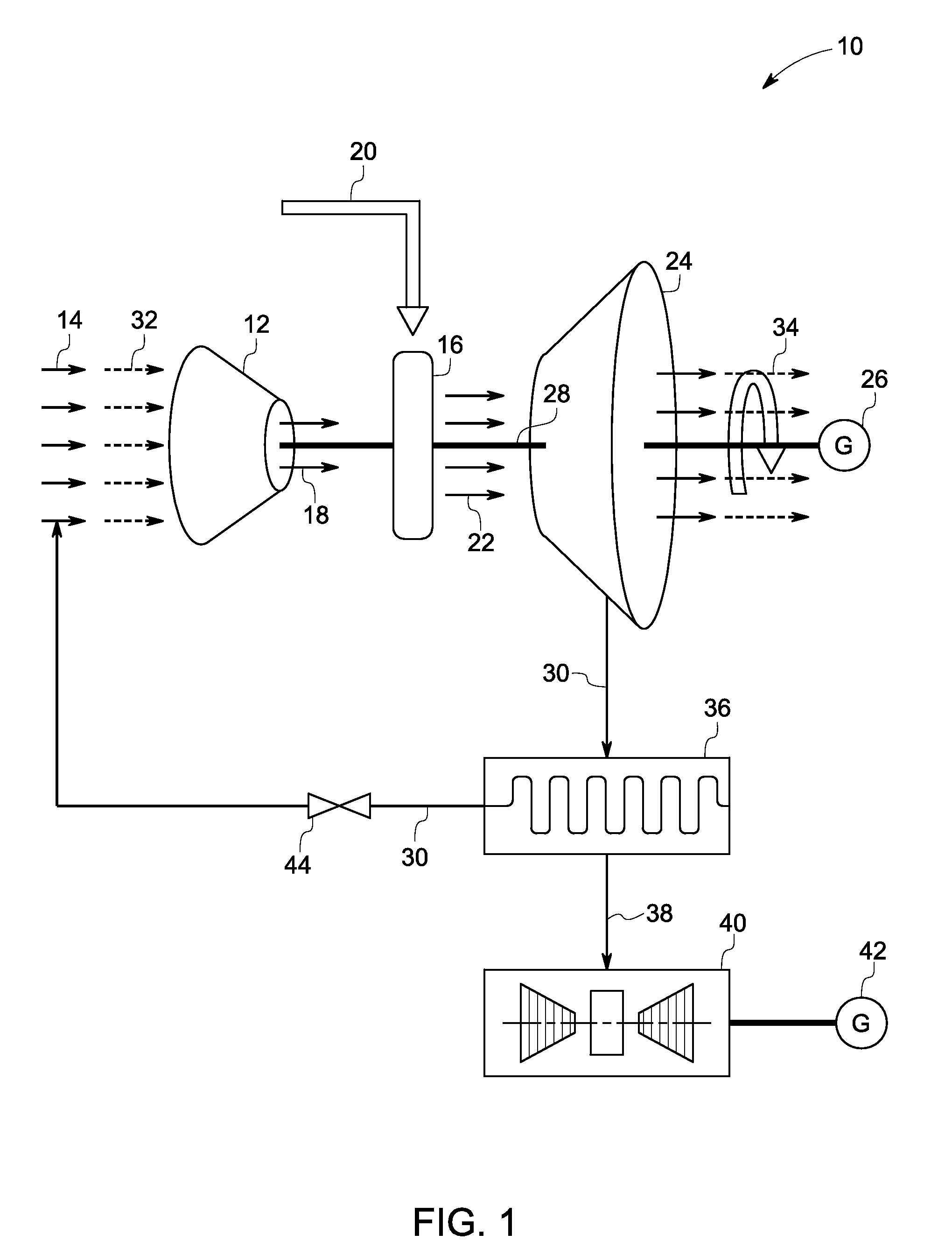
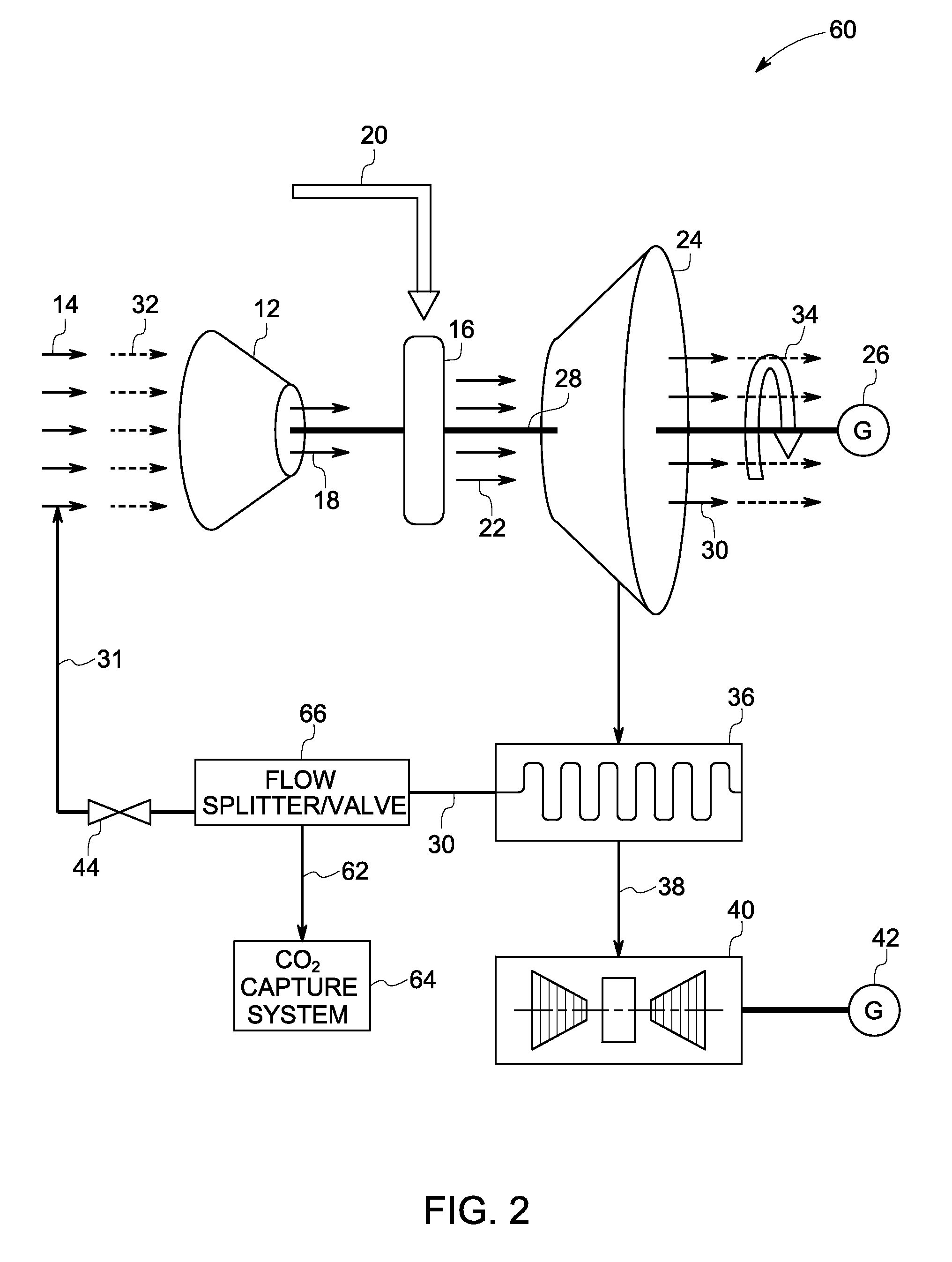
[0020]As discussed in detail below, embodiments of the present technique function to reduce emissions in turbine systems, and to provide combustion technologies to enhance overall efficiency of the turbine systems, while reducing NOx formation. In some of the specific embodiments, the present technique includes employing exhaust gas recirculation (EGR), along with a rich-quench-lean (RQL) mode of combustion to minimize emissions such as NOx.

[0021]Turning now to the drawings and referring first to FIG. 1 a turbine system 10 is illustrated. The turbine system 10 includes a compressor 12 configured to compress ambient air 14. Further, the turbine system 10 includes a combustor 16 that is in flow communication with the compressor 12. The combustor 16 is configured to receive compressed air 18 from the compressor 12, and to combust a fuel stream 20 to generate an exhaust gas 22. In one exemplary embodiment, the combustor 16 includes a Dry Low Emission (DLE) or a Dry Low NOx (DLN) combust...


PUM


Abstract

A turbine system is provided. The turbine system includes a compressor configured to compress ambient air and a combustor configured to receive compressed air from the compressor, and to combust a fuel stream to generate an exhaust gas. The turbine system also includes a turbine for receiving the exhaust gas from the combustor to generate electricity; wherein a first portion of the exhaust gas is mixed with the ambient air to form a low-oxygen air stream, and wherein the low-oxygen air stream is compressed using the compressor, and is directed to the combustor for combusting the fuel stream to generate a low-NOx exhaust gas.

Description

BACKGROUND[0001]The invention relates generally to turbine systems, and more particularly to, low emission turbine systems and methods.[0002]Various types of gas turbine systems are known and are in use. For example, aeroderivative gas turbines are employed for applications such as power generation, marine propulsion, gas compression, cogeneration, offshore platform power and so forth. Typically, the gas turbines include a compressor for compressing an air flow and a combustor that combines the compressed air with fuel and ignites the mixture to generate an exhaust gas. Further, the exhaust gas is expanded through a turbine for power generation.[0003]Typically, the combustors for such systems are designed to minimize emissions such as NOx and carbon monoxide (CO) emissions. In certain traditional systems, lean premixed combustion technology is employed to reduce the emissions from such systems. Typically, NOx emissions are controlled by reducing the flame temperature in the reaction...

Claims


Application Information

Patent Timeline
Patent Type & Authority Applications(United States)
IPC IPC(8): F01D15/10F02C3/30F02C7/08
CPCF01K23/10Y02E20/18Y02E20/14F02C3/34
Inventor ELKADY, AHMED MOSTAFAEVULET, ANDREI TRISTAN
Owner GENERAL ELECTRIC CO
Why Eureka
Try Eureka