Method of operating a combustion system for increased turndown capability

a combustion system and turndown capability technology, applied in the direction of machines/engines, mechanical equipment, lighting and heating apparatus, etc., can solve the problems of inability to operate efficiently at lower load settings, unstable combustion systems of the prior art, and inability to produce acceptable levels of carbon monoxide (co) and oxides of nitrogen (nox), so as to achieve low emissions and control the effect of emissions

Active Publication Date: 2006-11-21
ANSALDO ENERGIA SWITZERLAND AG
View PDF26 Cites 154 Cited by
  • Summary
  • Abstract
  • Description
  • Claims
  • Application Information

AI Technical Summary

Benefits of technology

[0010]It is through axial, radial, and circumferential fuel staging described herein that low emissions and stable combustion is maintained throughout all points of the engine operating cycle. By decreasing fuel flow split to active injectors when additional injectors are started, emissions levels are controlled. At the first part-load condition, when only first and second injectors are operating, flame temperature will tend to be higher due to the locally high operating fuel / air ratio. As a result, the higher flame temperature precludes the release of CO while assuring a stable flame at the first part-load condition. As load increases, fuel flow split to the pilot region proximate the igniter is reduced and additional fuel-air mixing is accomplished from the aft injector assembly.

Problems solved by technology

Combustion systems of the prior art have been known to become unstable at lower load settings while also producing unacceptable levels of carbon monoxide (CO) and oxides of nitrogen (NOx) at these lower load settings, especially below 50% load.
This is primarily due to the fact that most combustion systems are staged for most efficient operation at high load settings and therefore operate less efficiently at lower load settings.
While this staging method and combustor configuration is an enhancement, it is still limited in turndown capability, such that in order to achieve turndown to low, part-load settings, the combustor must often revert to the higher emissions diffusion mode and not operate in the lower emissions premix mode.
The combination of potentially unstable combustion and higher emissions often times prevents engine operators from running engines at lower load settings, forcing the engines to either run at higher settings, thereby burning additional fuel, or shutting down, and thereby losing valuable revenue that could be generated from the part-load demand.
A further problem with shutting down the engine is the additional cycles that are incurred by the engine hardware.
Therefore, incurring additional cycles can reduce hardware life requiring premature repair or replacement at the expense of the engine operator.

Method used


Image

  • Method of operating a combustion system for increased turndown capability
  • Method of operating a combustion system for increased turndown capability
  • Method of operating a combustion system for increased turndown capability

Examples


Embodiment Construction

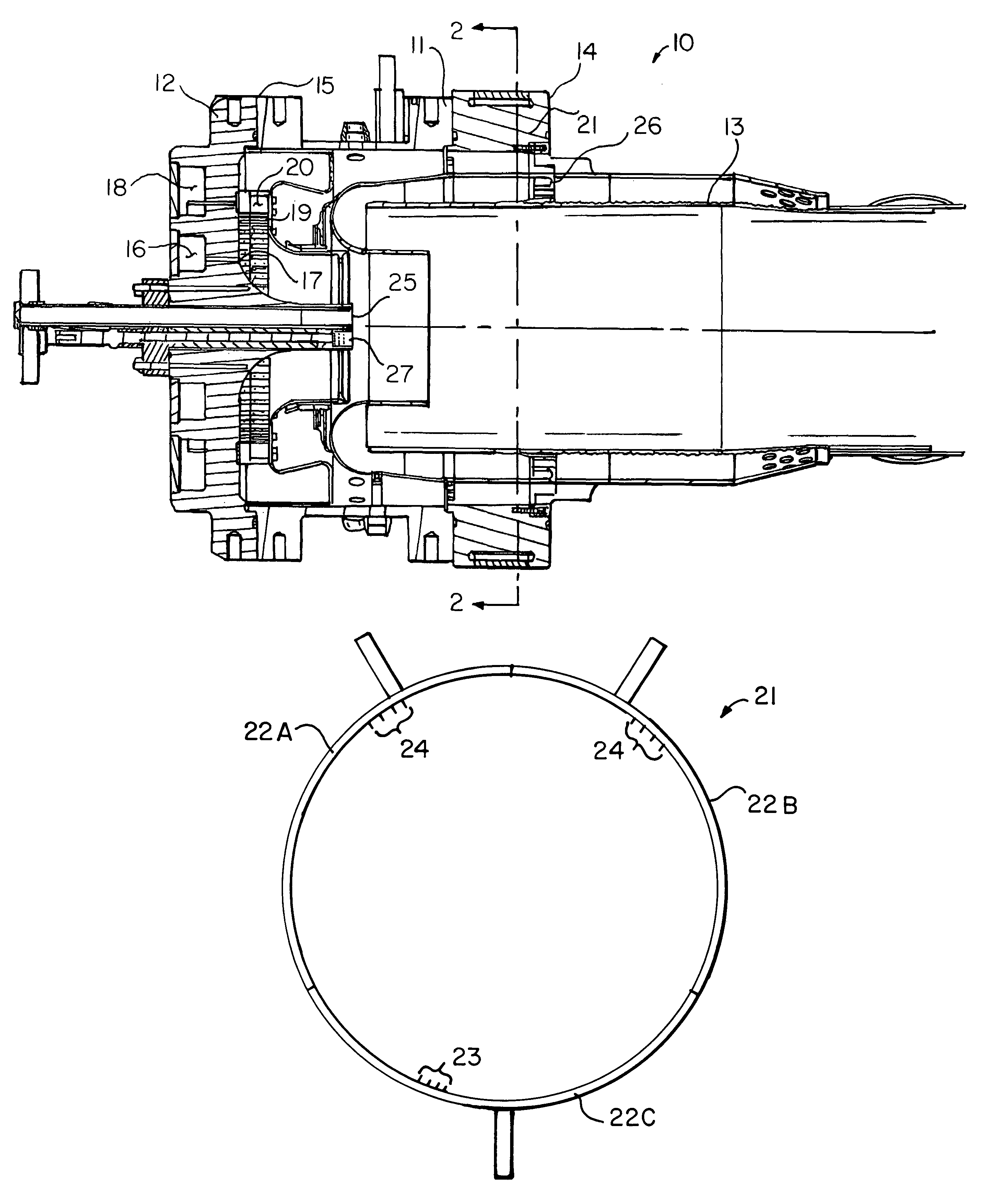
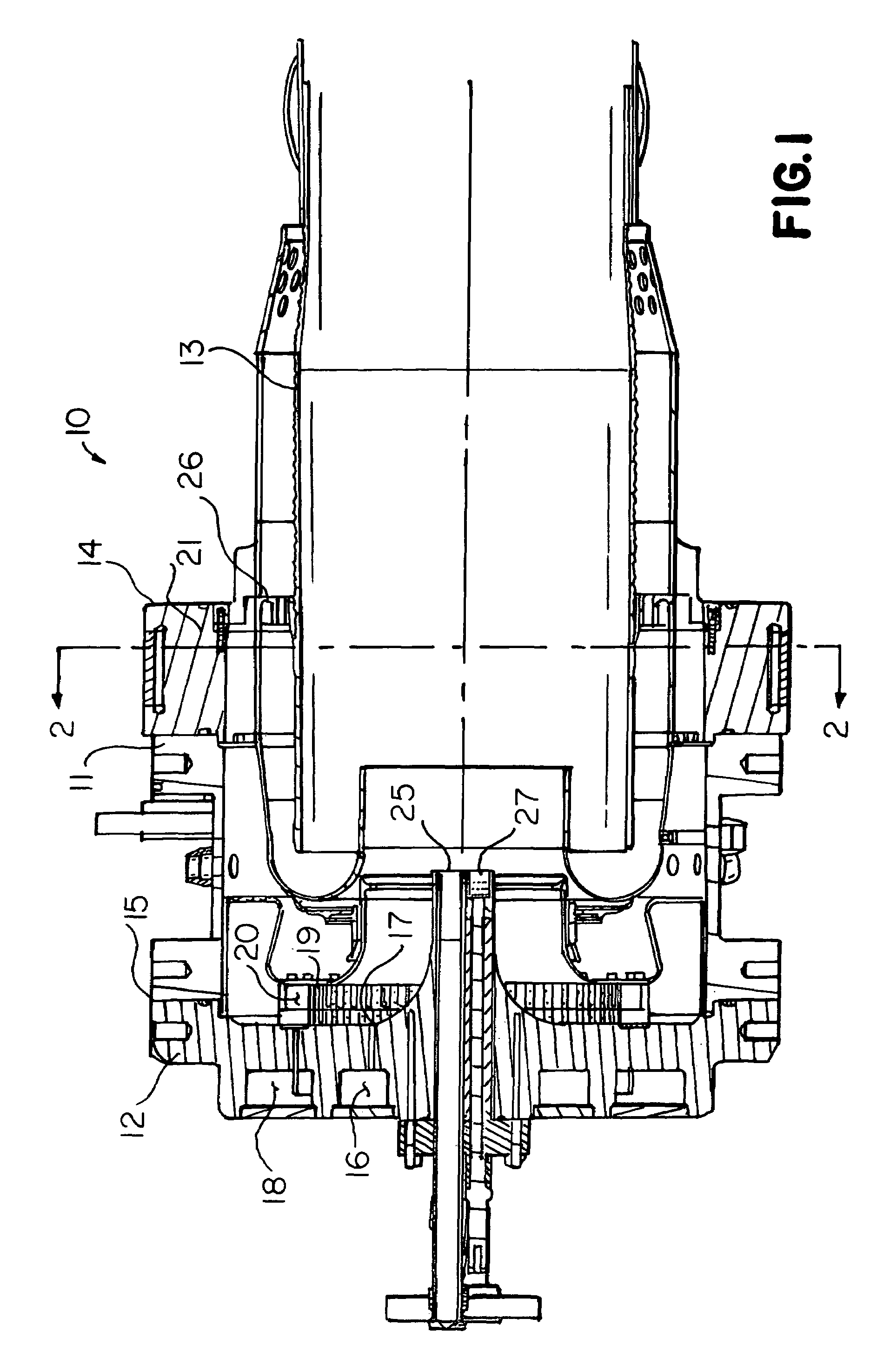
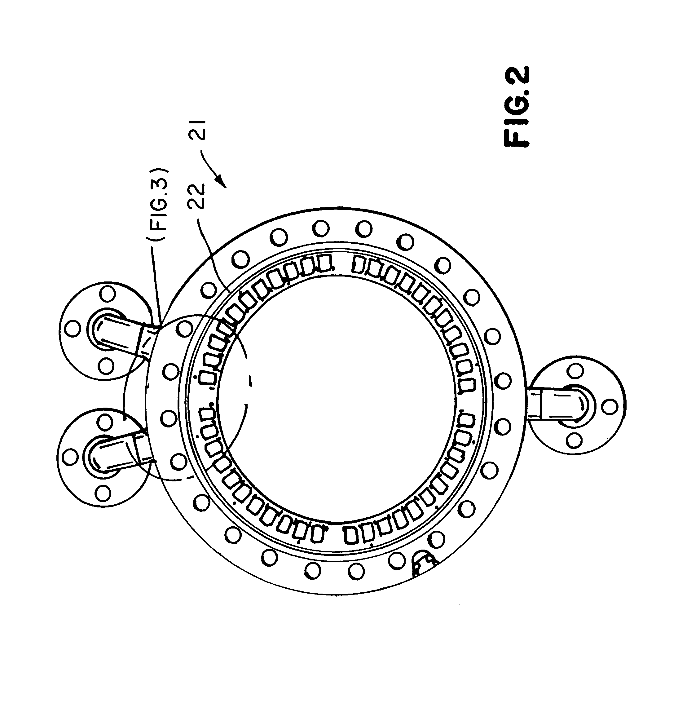
[0018]Referring to FIG. 1, a combustion system 10 for a gas turbine engine is shown in cross section. Combustion system 10 comprises casing 11, end cover 12, combustion liner 13, and a center axis A—A. Casing 11, which is mounted to an engine through flange 14, is in fluid communication with compressed air from a compressor. An end cover 12 is fixed to casing first end 15, with end cover 12 having at least one fuel source in fluid communication with at least one set of injectors. In the preferred embodiment a first fuel source 16 is in fluid communication with a plurality of first stage injectors 17, where plurality of first stage injectors 17 are arranged in a first array about center axis A—A. Furthermore, the preferred embodiment of end cover 12 also contains a second fuel source 18 in fluid communication with a plurality of second stage injectors 19, where plurality of second stage injectors 19 are arranged in a second array radially outward of first stage injectors 17 proximate...


PUM


Abstract

A method of operating a gas turbine engine combustion system at lower load conditions while maintaining required emissions levels is disclosed. The present invention includes multiple embodiments of axial, radial, and circumferential fuel staging within a can-type combustor having alternate ignition techniques of spark ignition or torch ignition.

Description

BACKGROUND OF THE INVENTION[0001]This invention relates in general to gas turbine combustion systems and specifically to a method of operating a gas turbine combustion system at significantly lower load conditions while having stable combustion and lower emissions.[0002]Gas turbine engines typically include a compressor, one or more combustors each having a fuel injection system, and a turbine section. In an engine having a plurality of combustors, they are typically arranged in an annular array about the engine and most typically interconnected for the purposes of ignition. The compressor raises the pressure of inlet air, and then directs it to the combustors, where it is used to cool the combustion chamber walls as well to provide air for the combustion process. In the combustion chamber, compressed air is mixed with a fuel and the mixture is ignited by an ignition source to produce hot combustion gases. Typically, ignition occurs within a single chamber, and for engines with mult...

Claims


Application Information

Patent Timeline
Patent Type & Authority Patents(United States)
IPC IPC(8): F02C9/00
CPCF02C7/228F23R3/343
Inventor STUTTAFORD, PETERMARGARIT-BEL, NURIACHEN, YANOUMEJJOUD, KHALIDJENNINGS, STEPHEN
Owner ANSALDO ENERGIA SWITZERLAND AG
Why Eureka
Try Eureka