
Polarization structure with touch function

Inactive Publication Date: 2014-06-19
LIN CHIH CHUNG
View PDF3 Cites 15 Cited by
  • Summary
  • Abstract
  • Description
  • Claims
  • Application Information

AI Technical Summary

Benefits of technology

The present invention provides a polarization structure with touch functions that has a higher manufacturing yield and lower manufacturing cost. Additionally, it is easy to produce, assemble, and maintain. The design includes a first polarization plate, transparent plate, conductive glue layer, and adhesive layer. This results in a touch-functional LCD module with simplified production and assembly processes, and convenient replacement or maintenance. The combination of the first polarization plate and the inductive electrode layer on the transparent plate effectively fulfills touch functions.

Problems solved by technology

The LCD device of the prior art provides only video images for observers and can not provide the touch functions for interaction with the observers; hence an embedded touch LCD device has been developed by the industry.
Though the embedded touch LCD device of the prior art has the touch function, another problem occurs.
That is the manufacturing process of the display panel of the LCD device of the prior art is different from that of the embedded touch LCD device such that a simplified manufacturing process can not be achieved and because the touch sensing electrodes of the embedded touch LCD device are disposed in the display panel, it is really difficult to maintain or replace the touch sensing electrodes when damage or contact failure of the touch sensing electrode is detected.
Accordingly, the glass substrate and touch sensing electrodes thereon in a new display panel have to be replaced and the manufacturing cost is increased.
1. low manufacturing yield;
2. increased manufacturing cost; and
3. the production and assembling processes can not be simplified and the sensing electrodes can not be uninstalled, inspected, and maintained easily.

Method used


Image

  • Polarization structure with touch function
  • Polarization structure with touch function
  • Polarization structure with touch function

Examples


Embodiment Construction

[0029]The above objectives of the present invention and the features of structure and function of the present invention are described according to preferred embodiments in figures.

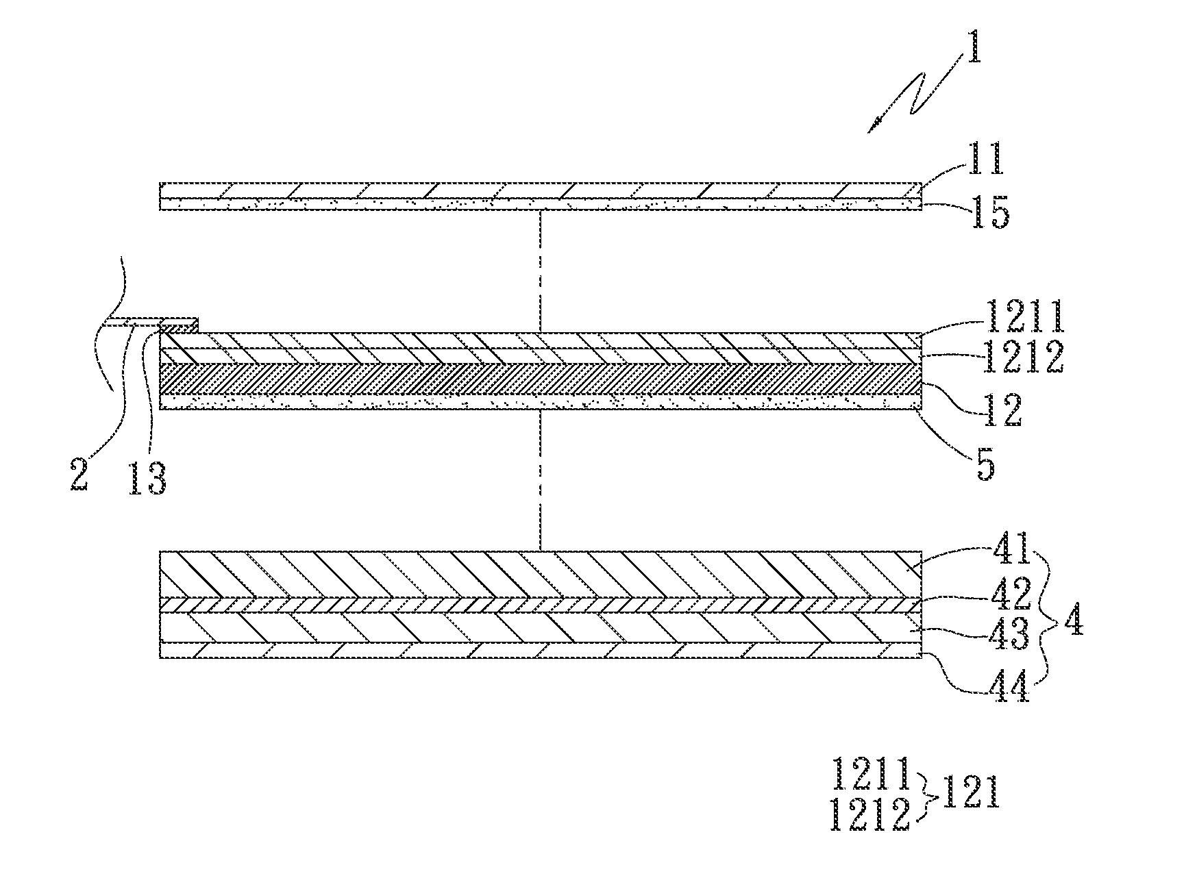
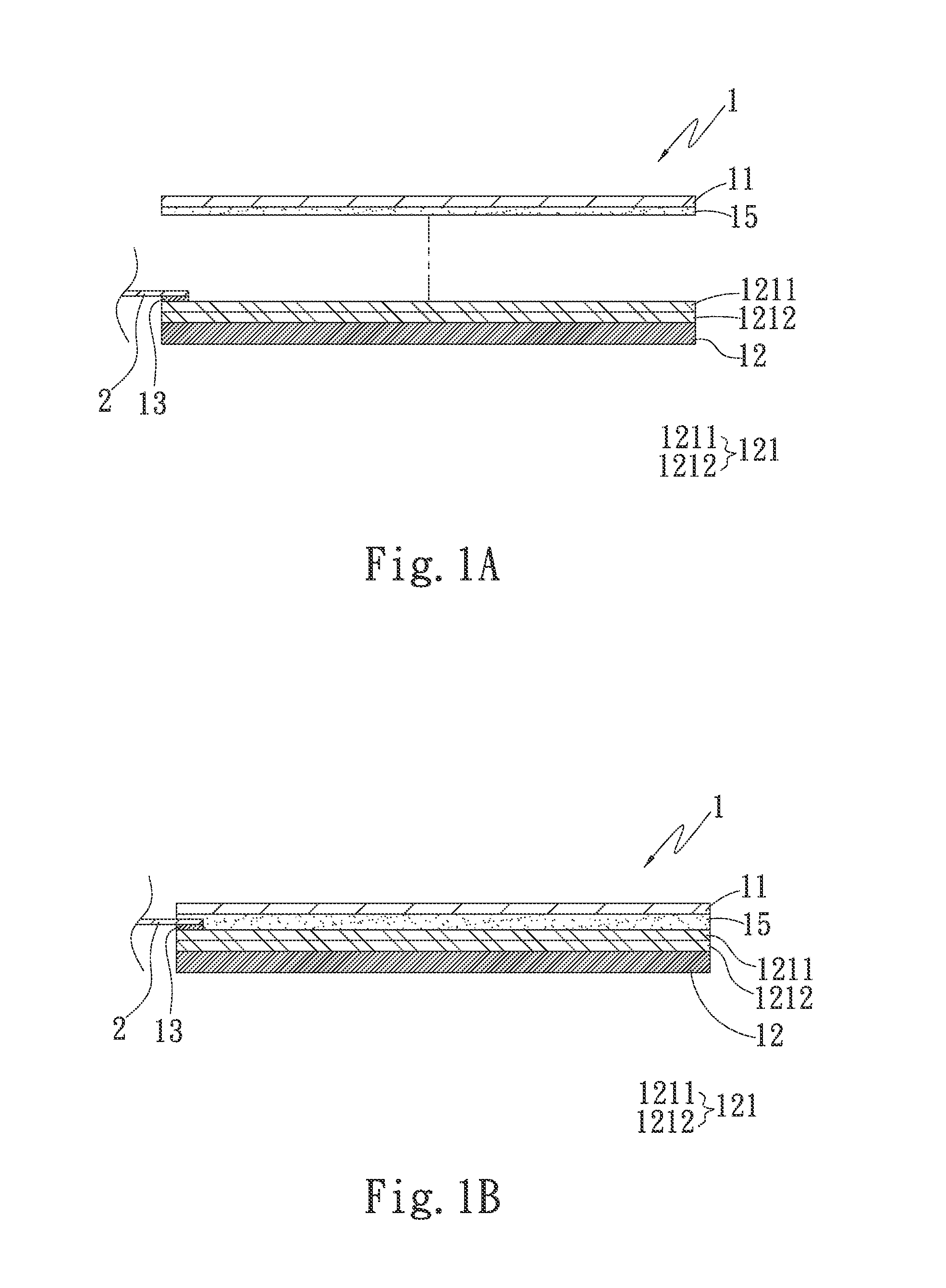
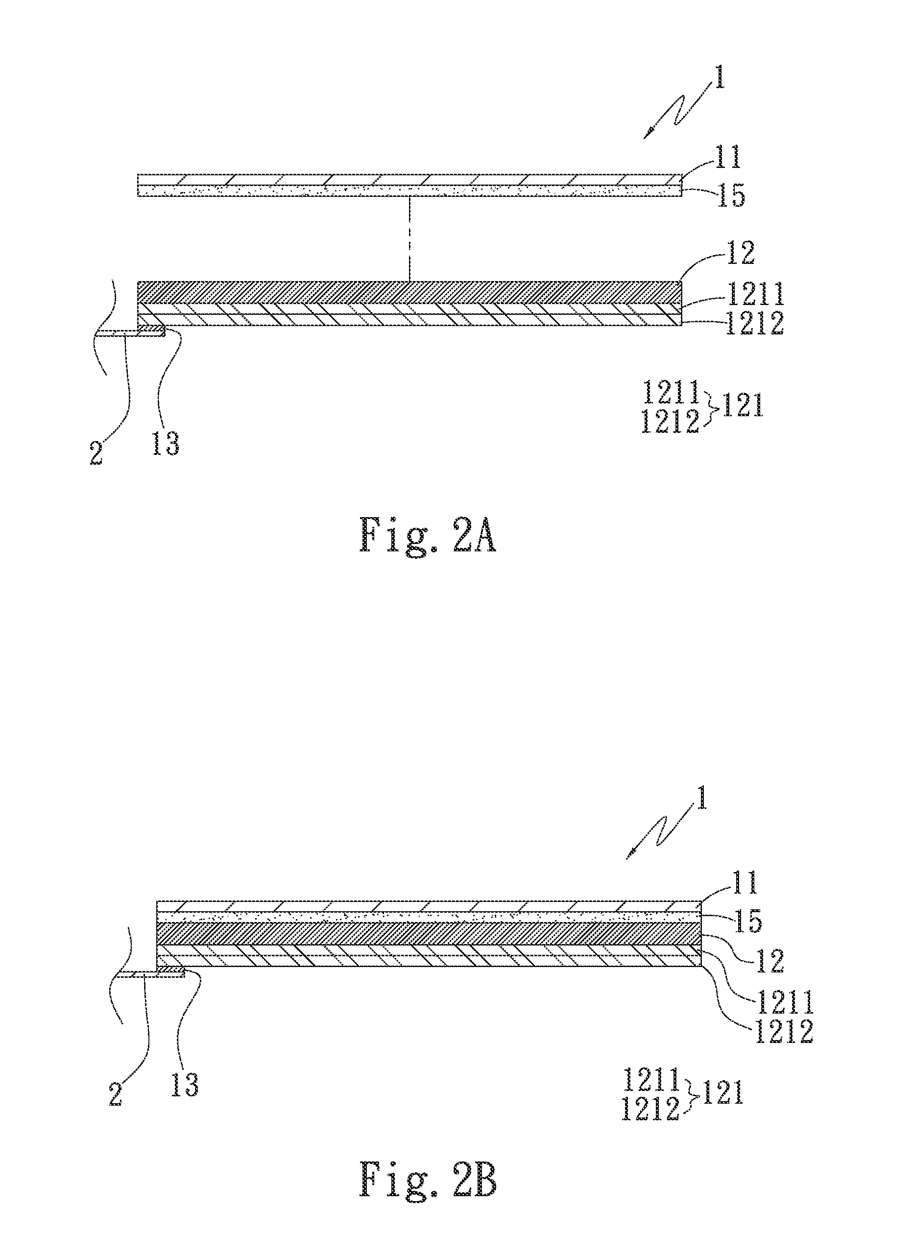
[0030]The present invention provides a polarization structure with touch functions, referring to FIGS. 1A and 1B which are an exploded cross-sectional view and a combined cross-sectional view of the polarization structure according to the first embodiment of the present invention, respectively. The polarization structure 1 includes a first polarization plate 11, a transparent substrate 12, a first conductive glue layer 13, and a first adhesive layer 15. The first adhesive layer 15 is optical clear adhesive (OCA), optical clear resin (OCR), or liquid adhesive lamination (LAL). The first adhesive layer 15 is disposed between the first polarization plate 11 and the transparent substrate 12, whereby to attach the first polarization plate 11 to the transparent substrate 12.

[0031]Also, the side of the first pola...


PUM


Abstract

The present invention provides a polarization structure with touch functions, including a first polarization plate, a transparent substrate having an inductive electrode layer, a first conductive glue layer, and a first adhesive layer, one side of the first conductive glue layer being attached to the inductive electrode layer and the other side thereof being attached to an FPC, the first adhesive layer being disposed between the first polarization plate and the transparent substrate, whereby the first polarization plate is attached to the transparent substrate. The structure of the present invention is applied to an LCD module and thus the manufacturing yield can be increased and the touch functions can be fulfilled.

Description

[0001]This application claims the priority benefit of Taiwan patent application number 101148204 filed on Dec. 19, 2012.BACKGROUND OF THE INVENTION[0002]1. Field of the Invention[0003]The present invention relates to a polarization structure and in particular to a polarization structure with touch functions and high manufacturing yield.[0004]2. Description of Prior Art[0005]Recently, various flat display devices have been developed, such as the liquid crystal display (LCD), field emission display (FED), plasma display panel (PDP), and light emitting display (LED). Among the above flat display devices, the LCD device has been widely used due to advantageous features such as low power consumption, thin profile, and enhanced brightness.[0006]The LCD device of the prior art provides only video images for observers and can not provide the touch functions for interaction with the observers; hence an embedded touch LCD device has been developed by the industry. During the assembling of the...

Claims


Application Information

Patent Timeline
IPC IPC(8): G02F1/1333G06F3/041
CPCG06F3/0412G06F2203/04103G02F1/133528G02B5/3025G02F2202/28G02F1/13338G06F3/0443G06F3/04164
Inventor LIN, CHIH-CHUNG
Owner LIN CHIH CHUNG
Learn More