Passive matrix OLED display having increased size

a matrix oled display and matrix technology, applied in the field of oled displays, can solve the problems of imposing practical constraints on the overall display size, pixel cost and complexity of these devices, and current-carrying requirements for driver support components, etc., and achieve the effect of sufficient brightness

Inactive Publication Date: 2006-05-04
EASTMAN KODAK CO
View PDF15 Cites 69 Cited by
  • Summary
  • Abstract
  • Description
  • Claims
  • Application Information

AI Technical Summary

Benefits of technology

[0024] It is an object of the present invention to provide a large-scale OLED display having sufficient brightness using a passive-matrix OLED design. With this object in mind, the present invention in one embodiment provides a passive matrix OLED display comprising an array of individually addressable OLED pixels arranged in column and row lines in an imaging area of the display, wherein the display has a diagonal dimension in excess of 10 inches and has more than 150 row lines in the imaging region, and is free of line dropout defects in the image region and provides a maximum full-frame brightness of at least 50 nits.
[0026] From another aspect, various embodiments of the present invention provide a passive matrix OLED display exhibiting, over its operating range, increasing efficiency with increasing drive current density. It is a feature of an embodiment of the present invention that it provides an OLED display using stacked OLEDs in a passive matrix design. The apparatus of various embodiments of the present invention takes advantage of the improved light efficiency of the stacked OLED design providing singlet exciton emission, while enjoying the advantage of simplicity over alternative active-matrix design solutions.
[0027] It is an advantage of various embodiments of the present invention that it provides increased display brightness over previous designs and, unlike conventional OLED devices, provides improved efficiency with increased current density.
[0028] It is an advantage of various embodiments of the present invention that it provides improved manufacturing yields for a large-scale OLED matrix.
[0029] It is an advantage of various embodiments of the present invention that it is capable of providing improved display resolution over previous designs.

Problems solved by technology

In an active matrix OLED display, each pixel requires built-in switching transistors and other control circuitry, contributing to the cost and complexity of these devices, per pixel.
Among other factors, this requirement for high brightness imposes practical constraints on overall display size when using passive matrix designs.
A further disadvantage of these devices relates to current-carrying requirements for driver support components, needed to handle the momentary high-current pulse for each individual row of passive matrix OLED devices.
While smaller passive-matrix OLED displays of a few inches in diagonal have been successfully built, it is a common belief among researchers in the display arts that there are significant constraints inherent to large passive-matrix OLED designs.
This article states that efficiency limitations constrain the potential dimensions of passive-matrix OLED displays to no greater than 2-3 or 100 display lines.
Although passive matrix components have simpler fabrication than is needed for active matrix components, this advantage is largely eroded by the relative significance of defects for passive matrix design.
Fabrication defects present significant obstacles to the development of large area OLED displays of the passive matrix type.
Defects may be due to dust or contamination during fabrication, asperities due to electrode surfaces, pinholes, and non-uniformities in organic layer thickness, for example.
Whereas some number of individual dead pixels 10 can be tolerated in a viewed image, defects affecting an entire line, in general are not acceptable.
Even dim constant illumination of diode 11c would be undesirable.
The likelihood of a fabrication defect increases dramatically as the display area increases.
In other words, chances for a good display yield with a very large passive-matrix OLED display, using conventional techniques, are practically nil.
While this approach can mitigate defect problems, the array requires a considerable number of additional components, many of which would not be used.
Moreover, defects occurring after manufacture, and testing would still have a negative effect on display performance.
Another problem for large-scale display design using passive-matrix technology relates to luminous efficiency characteristics of OLEDs.
It is widely recognized that conventional efficiencies, typically on the order of a few cd / A (candelas per ampere), are insufficient for realizing large passive matrix displays.
Unfortunately, however, the luminous efficiency of these devices drops as a function of drive current density, as is described in U.S. Pat. No. 6,645,645 entitled “Phosphorescent Organic Light Emitting Devices” to Adachi et al. and in International Application, Publication Number WO 00 / 70655 entitled “Very High Efficiency Organic Light Emitting Devices Based on Electrophosphorescence” by Baldo et al.
Because passive matrix addressing requires much higher drive current densities than are typically needed for active matrix devices, the compromised efficiency of these devices with increased current levels does not at all suggest passive matrix technology as a promising solution for the problem of obtaining higher brightness levels.
However, prior art again shows that, for triplet emission components, luminous efficiency degrades as a function of current density.
To date, then, a number of problems have prevented the development and commercialization of large area OLED displays of the passive matrix type.
Frustrated by low fabrication yields, performance constraints, relatively high power consumption, efficiency drop-off at high current densities, and brightness limitations of conventional passive-matrix design approaches, researchers interested in large-scale QLED displays have primarily focused on active-matrix, rather than passive-matrix OLED designs.
While there have been a few solutions proposed for limiting or minimizing the impact of a faulted OLED on other nearby OLEDs, none of these solutions is particularly well suited for use with a passive matrix OLED array used in imaging display applications, where each OLED electroluminescent diode 11 serves as one individually addressable pixel 10 for forming an image.

Method used


Image

  • Passive matrix OLED display having increased size
  • Passive matrix OLED display having increased size
  • Passive matrix OLED display having increased size

Examples


Embodiment Construction

[0043] The present description is directed in particular to elements forming part of, or cooperating more directly with, apparatus in accordance with the invention. It is to be understood that elements not specifically shown or described may take various forms well known to those skilled in the art.

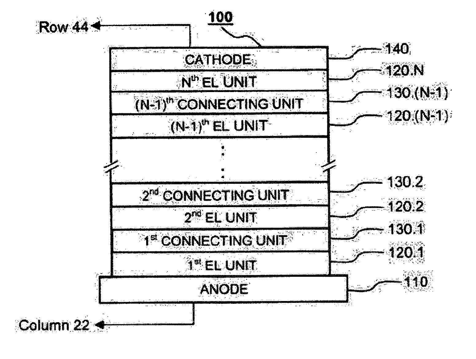
[0044] For commercial viability, a high-brightness display using OLED emitters must typically provide full-frame brightness of at least a threshold level of 50 nits or better. Additionally, there must be no line dropout defects in the image region of the display, such that a complete column or row of pixels is disabled by a faulted element of the display. While current designs employing passive-matrix OLED displays are typically limited to display screens having no more than about 100 row lines and being no greater than about 6 inches diagonally, the present invention enables passive-matrix OLED displays having substantially increased size and brightness. As the background material given...


PUM


Abstract

A passive matrix OLED display free of line dropout defects in the image region and providing full-frame brightness of at least 50 nits is disclosed. In one embodiment of the invention, the display may have a diagonal surface dimension in excess of 10 inches and may have more than 150 row lines. In a specific embodiment, a passive matrix OLED display is described comprising an array of individually addressable OLED pixels arranged in column and row lines in an imaging area of the display, wherein at least one pixel comprises at least one current-limiting component connected in series with an electroluminescent diode, and wherein the electroluminescent diode comprises a plurality of electroluminescent units connected in series between an anode and a cathode.

Description

FIELD OF THE INVENTION [0001] This invention generally relates to OLED displays and more particularly relates to a passive matrix OLED display having significantly increased surface area and brightness over previous passive matrix OLED designs. BACKGROUND OF THE INVENTION [0002] Organic Light Emitting Diode (OLED) technology holds significant promise as a display technology that is well-suited to a broad range of applications. Self-emitting OLED displays are advantaged over other display technologies, requiring no external light source and supporting optics and providing high luminance, good quality color, and relatively wide viewing angle. OLED display components are thin and lightweight, making them particularly adaptable for use with handheld components, such as cameras, cell phones, personal digital assistants (PDAs) and laptop computing devices. [0003] The basic bottom-emitting OLED pixel 10 is constructed as shown in FIG. 1. An organic layer 12, typically fabricated as a stack...

Claims


Application Information

Patent Timeline
Patent Type & Authority Applications(United States)
IPC IPC(8): H05B33/00H05B33/02H05B33/10
CPCH01L27/3204H01L27/3281H01L27/3293H01L51/5278H10K59/86H10K59/17H10K59/18H10K50/19
Inventor AGOSTINELLI, JOHN A.KOWARZ, MAREK W.LIAO, LIANG-SHENG
Owner EASTMAN KODAK CO
Why Eureka
Try Eureka