Vehicle headlamp

a headlamp and projector technology, applied in fixed installation, lighting and heating equipment, transportation and packaging, etc., can solve the problems of insufficient brightness of the diffusing region of the light distribution pattern, inability to control the brightness of the irradiated light with high precision, and the optical axis side region cannot be effectively utilized for light distribution control, etc., to achieve high precision, increase the amount of light, and sufficient brightness

Inactive Publication Date: 2005-10-13
KOITO MFG CO LTD
View PDF20 Cites 39 Cited by
  • Summary
  • Abstract
  • Description
  • Claims
  • Application Information

AI Technical Summary

Benefits of technology

[0012] The invention has been made in consideration of such circumstances, and has an object to provide a vehicle headlamp which can maintain sufficient amount of brightness in the diffusing region of a light distribution pattern and can increase the light amount to be irradiated on the forward part of the vehicle, and furthermore, can control the irradiated light with high precision even though the structure of the side insertion type lighting unit is employed in the projector type vehicle headlamp.
[0013] The invention provides a structure in which the inserting and fixing position of a light source bulb with respect to a reflector is devised and a predetermined light transmitting member is provided, thereby achieving the object.

Problems solved by technology

Since the light source bulb is inserted and fixed into the reflector over the same horizontal plane, there are the following problems.
For this reason, the optical-axis side region cannot be utilized effectively for a light distribution control.
Therefore, there is a problem in that it is hard to maintain sufficient amount of the brightness of the diffusing region of the light distribution pattern.
In the structure of the side insertion type lighting unit, however, there is a problem in that the irradiated light cannot be controlled by the annular light transmitting member with high precision if the annular light transmitting member is simply provided.

Method used


Image

  • Vehicle headlamp
  • Vehicle headlamp
  • Vehicle headlamp

Examples


second embodiment

[0085] Next, description will be given to the invention.

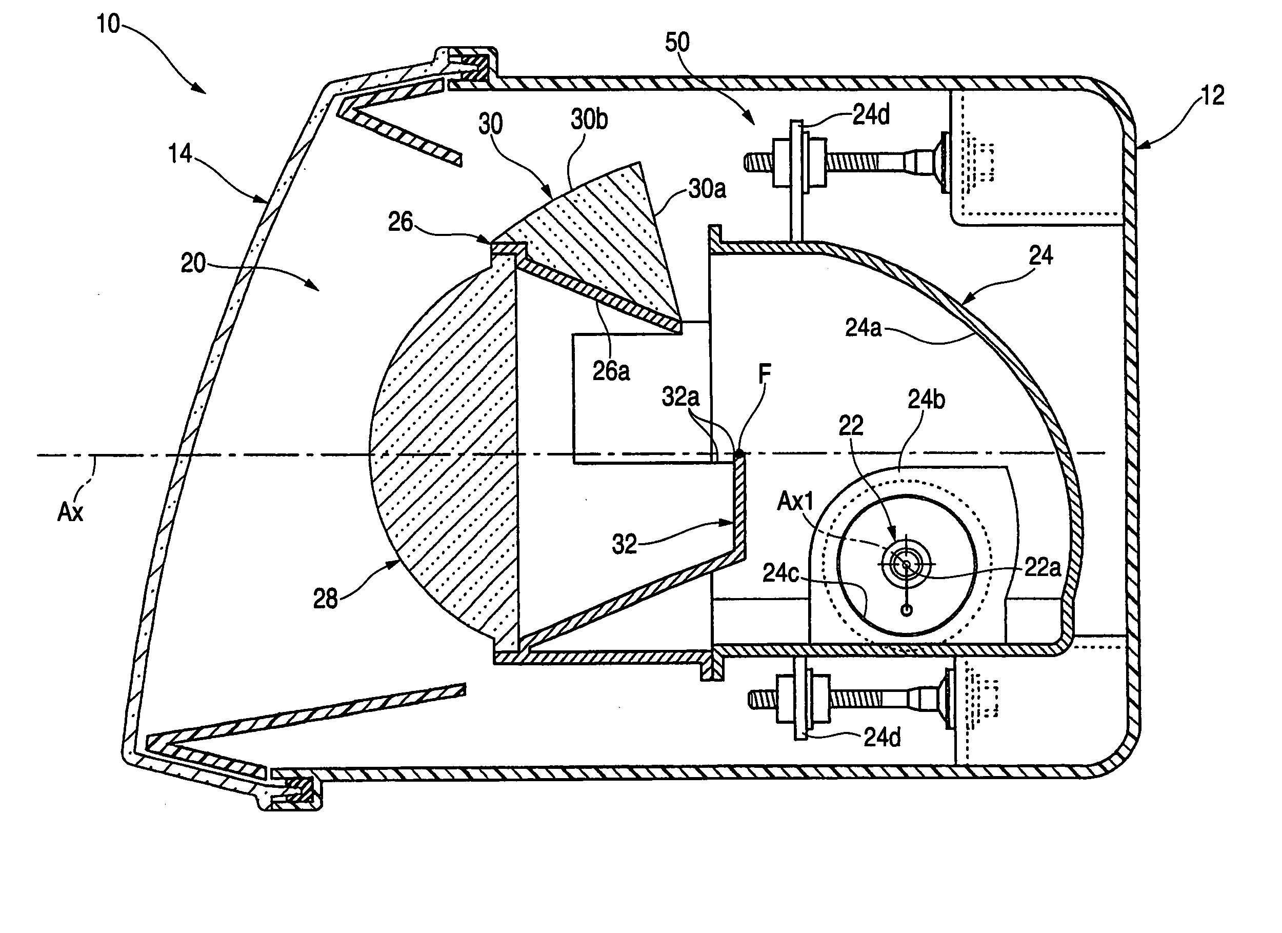
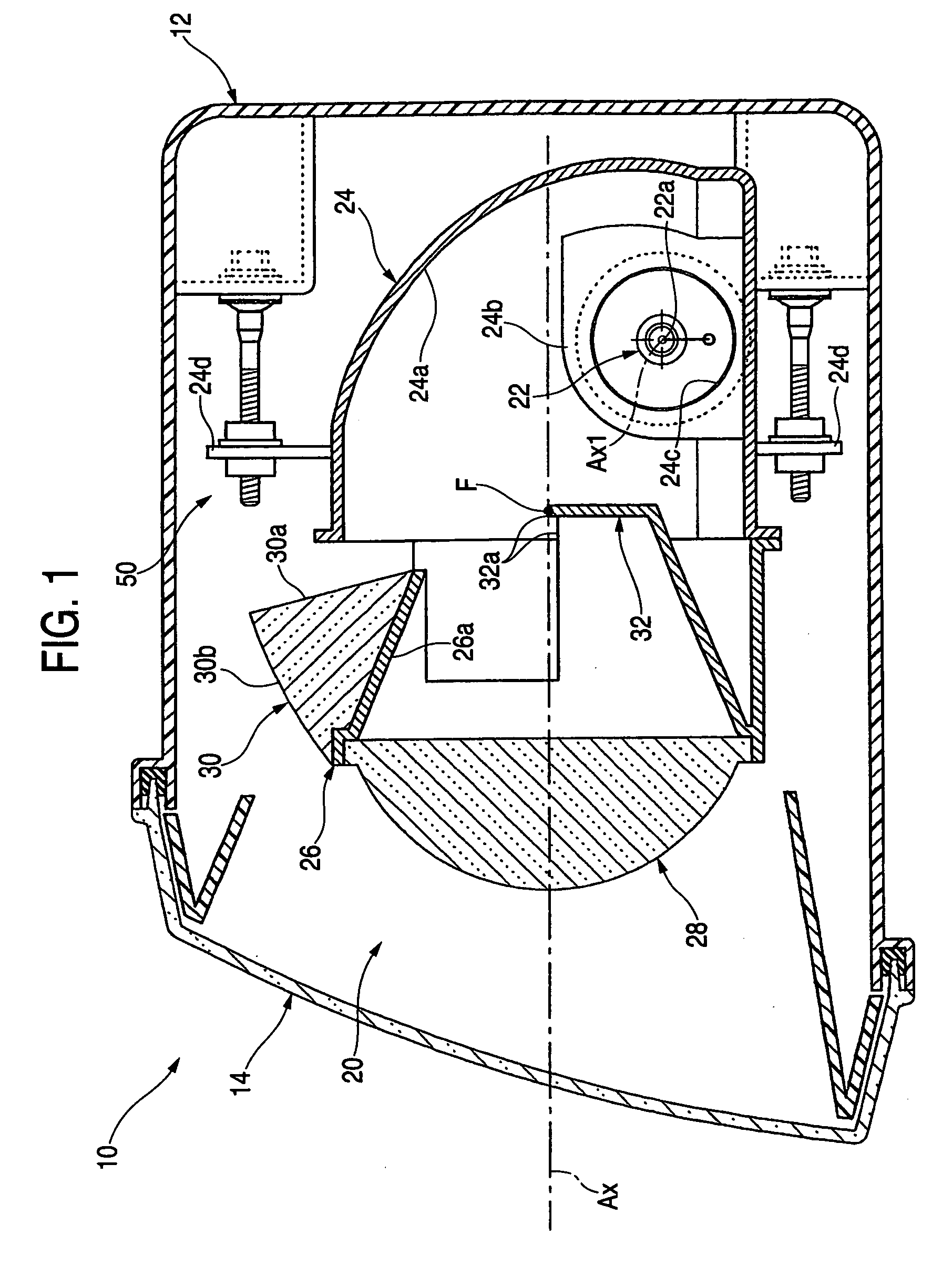
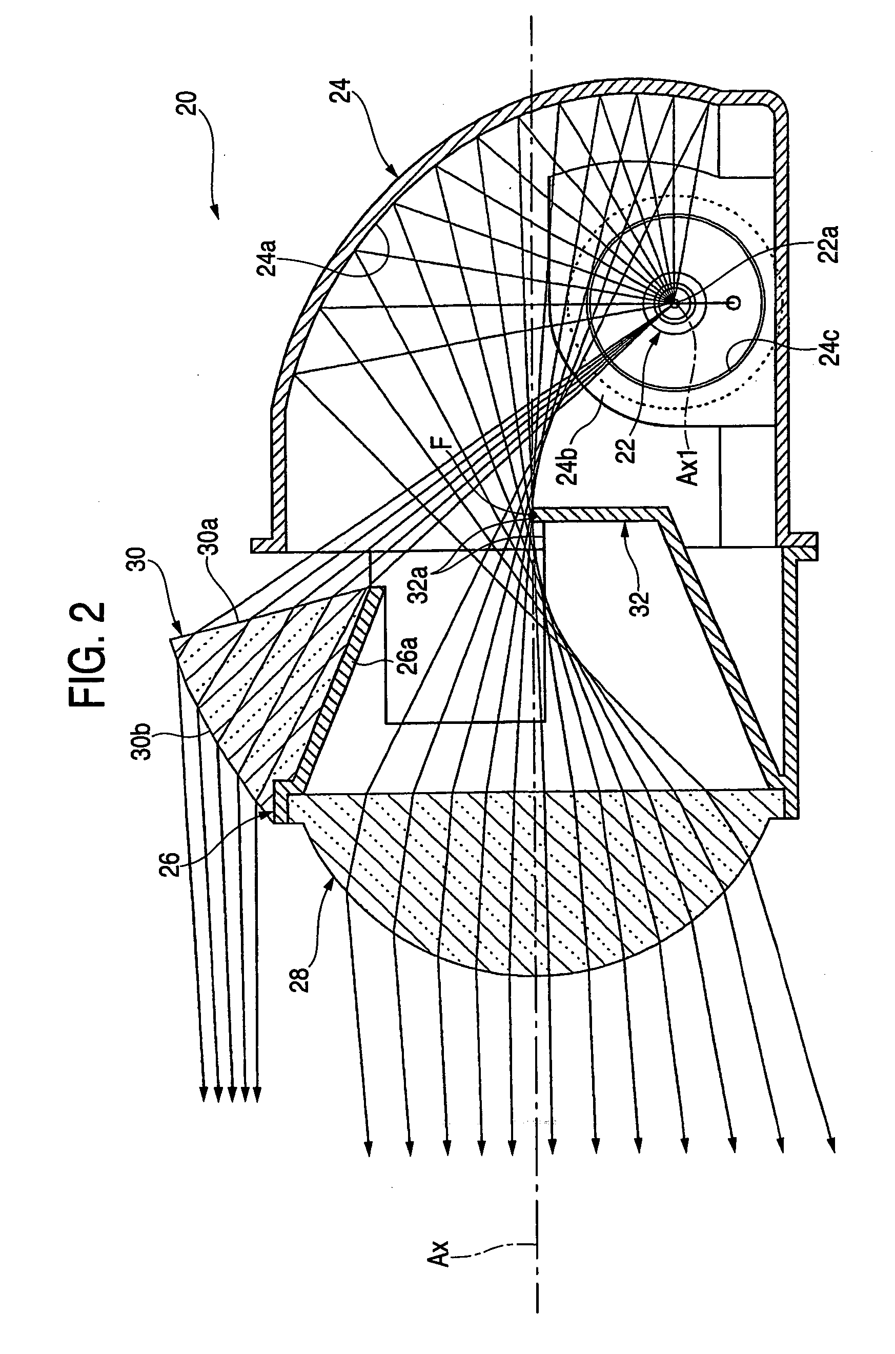
[0086]FIG. 6 is a sectional side view showing, as a single unit, a lighting unit 120 of a vehicle headlamp according to the embodiment.

[0087] As shown in FIG. 6, the basic structure of the lighting unit 120 is entirely the same as that in the first embodiment, and the structure of a light transmitting member 30 is different from that in the first embodiment.

[0088] More specifically, the light transmitting member 30 according to the embodiment is constituted as a reflection prism type light transmitting member comprising an internal reflecting plane 30c for internally reflecting, toward an emitting plane 30b, a direct light emitted from a light source 22a and incident on the light transmitting member 30, and has the same vertical sectional shape extended in a transverse direction.

[0089] In that case, an incidence plane 30a of the light transmitting member 30 has a vertical sectional shape set to be the shape of a circular arc...

first embodiment

[0096] Also in the case in which the structure according to the embodiment is employed, the direct light from the light source 22a toward the upper space of a projection lens 28 is emitted forward to be deflected downward by the light transmitting member 30 provided between the projection lens 28 and the reflector 24. Therefore, it is possible to obtain the same functions and advantages as those in the

[0097] In the embodiment, particularly, the light transmitting member 30 is constituted as a reflection prism type light transmitting member comprising the internal reflecting plane 30c. Therefore, it is possible to increase the degree of freedom of the shapes of the incidence plane 30a and the emitting plane 30b within such a range that a total reflection is not caused in the emitting plane 30b of the light transmitting member 30. Consequently, the direct light emitted from the light source 22a can be subjected to a deflection control with higher precision. Moreover, the degree of fre...

third embodiment

[0100] Next, description will be given to the invention.

[0101]FIG. 8 is a sectional side view showing, as a single unit, a lighting unit 220 of a vehicle headlamp according to the embodiment.

[0102] As shown in FIG. 8, the basic structure of the lighting unit 220 is entirely the same as that in the second embodiment, and the structure of a light transmitting member 30 is different from that in the second embodiment and is different from that in the second embodiment in that an additional reflector 34 is provided on the rear side of the light transmitting member 30.

[0103] The additional reflector 34 is constituted to reflect a direct light from a light source 22a toward the incidence plane of the light transmitting member 30. In that case, the vertical sectional shape of a reflecting plane 34a of the additional reflector 34 is set to be a hyperbolic shape in which a predetermined point A positioned above an optical axis Ax is a conjugate focal point with the light source 22a. In a v...


PUM


Abstract

A light source bulb 22 is inserted and fixed into a reflector 24 from a side in a position placed downward apart from an optical axis Ax. Thus; it is possible to effectively utilize an optical-axis side region in a reflecting plane 24a for a light distribution control. Moreover, an almost prism-shaped light transmitting member 30 is provided in the vicinity of the upper end of the outer peripheral edge portion of a projection lens 28 between the projection lens 28 and the reflector 24, and a direct light from a light source 22a toward the upper space of the projection lens 28 is emitted forward to be deflected downward. Consequently, it is possible to increase the amount of a light to be irradiated on the forward part of a vehicle, and furthermore, to carry out a deflection control for the direct light emitted from the light source 22a with high precision.

Description

[0001] This application claims foreign priority based on Japanese Patent application No. 2004-056873, filed Mar. 1, 2004, the contents of which is incorporated herein by reference in its entirety. BACKGROUND OF THE INVENTION [0002] 1. Field of the Invention [0003] The present invention relates to so-called projector type vehicle headlamp. [0004] 2. Description of the Related Art [0005] In general, a projector type vehicle headlamp has such a structure that a projection lens is provided on an optical axis extended in the longitudinal direction of the vehicle, and furthermore, a light source is provided on a rear side from a focal point on a back side thereof and a light emitted from the light source is reflected toward the optical axis by means of a reflector. [0006] As disclosed in JP(UM) Hei 2-47704 and JP(A) 2001-229715, there described the structure of a so-called side insertion type lighting unit in which a light source is constituted by the light emitting portion of a light sou...

Claims


Application Information

Patent Timeline
Patent Type & Authority Applications(United States)
IPC IPC(8): F21S8/00F21S8/10F21S8/12F21V5/00F21V7/00F21V17/00F21W101/10F21Y101/00
CPCB60Q2300/45F21S48/1186F21S48/119F21V7/0091F21S48/1241F21S48/1388F21S48/1233F21S41/172F21S41/173F21S41/24F21S41/28F21S41/36F21W2102/18
Inventor KOMATSU, MOTOHIROHAYAKAWA, MICHIHIKO
Owner KOITO MFG CO LTD
Why Eureka
Try Eureka