
Mobile telephone device having camera and illumination device for camera

a mobile telephone and camera technology, applied in the field of cellular phones, can solve the problems of difficult to shoot a subject under low light conditions, large components, and limited size of image pickup devices and lenses, and achieve the effects of reducing the attenuation of illuminating light emitted from the light-emitting diode, improving the optical transmittance of the light distribution lens, and improving the light emitted toward the subj

Inactive Publication Date: 2005-11-17
MITSUBISHI ELECTRIC CORP
View PDF5 Cites 50 Cited by
  • Summary
  • Abstract
  • Description
  • Claims
  • Application Information

AI Technical Summary

Benefits of technology

[0013] In an aspect of the present invention, a cellular phone with a built-in camera is a cellular phone equipped with a camera that can take a moving picture of a subject, including a lighting device for lighting a subject by means of a light-emitting diode, a switching device for turning on the lighting device, a light distribution lens for condensing (collecting) light emitted from the lighting device onto the subject, and a transparent cover, disposed in the front, or on the subject side of the lighting device, for protecting the light distribution lens. A light utilizing a light-emitting diode is also provided. Accordingly, the size, weight, and profile (thickness) of the cellular phone can be reduced, and also, a subject can be continuously illuminated by the light while a moving picture is being taken by the camera. Because of the light distribution lens for condensing light emitted forward from the light-emitting diode onto the subject, light emitted from the light-emitting diode can be efficiently directed onto the subject.
[0024] In another aspect of the present invention, a cellular phone with a built-in camera has a lighting unit in which a highly reflective structure is provided as a reflection portion at least around a light-emitting diode, on a surface of the printed circuit board where the light-emitting diode is provided. The reflection portion is shaped to enclose or cover at least a part of the side wall of the light-emitting diode, and a structure having a highly reflective surface on the side of the subject is formed and fixed on the printed circuit board. The structure of the reflection portion is formed with a resin of a highly reflective color, which is white, yellow, silver, or gold, or at least has the surface of the subject side coated in white, yellow, silver or gold, which is a highly reflectivity color, or at least has the surface of the subject side covered by a metal film formed by coating or vapor deposition. Accordingly, the amount of attenuation of illuminating light emitted from the light-emitting diode can be suppressed greater than when a reflection portion only is provided. Light reflected from the surface of a light distribution lens, transparent cover, and the like toward the light-emitting diode side can be reflected back to the subject side in a shorter optical path than when a reflection portion is provided on the printed circuit board. Accordingly, optical transmittance of the light distribution lens, transparent cover, and the like can be improved. Therefore, the amount of light directed to the subject increases, improving the illuminance of the subject still further.

Problems solved by technology

The sizes of image pickup devices and lenses are limited, and the dimensions of the cellular phones should not be increased, so that it has been difficult to shoot a subject under low light conditions.
The conventional cellular phone with a built-in camera described above, however, requires relatively large components for a cellular phone, such as the xenon lamp, reflector, and large capacitor for charging, contrary to the user's demand for smaller, lighter, and thinner cellular phones.
However, no conventional cellular phones have a continuous lighting unit.
Accordingly, it is easy to visually recognize the xenon lamp of the strobe light unit added to the conventional cellular phone with a built-in camera, which would not be desirable in regard to the appearance.

Method used


Image

  • Mobile telephone device having camera and illumination device for camera
  • Mobile telephone device having camera and illumination device for camera
  • Mobile telephone device having camera and illumination device for camera

Examples


first embodiment

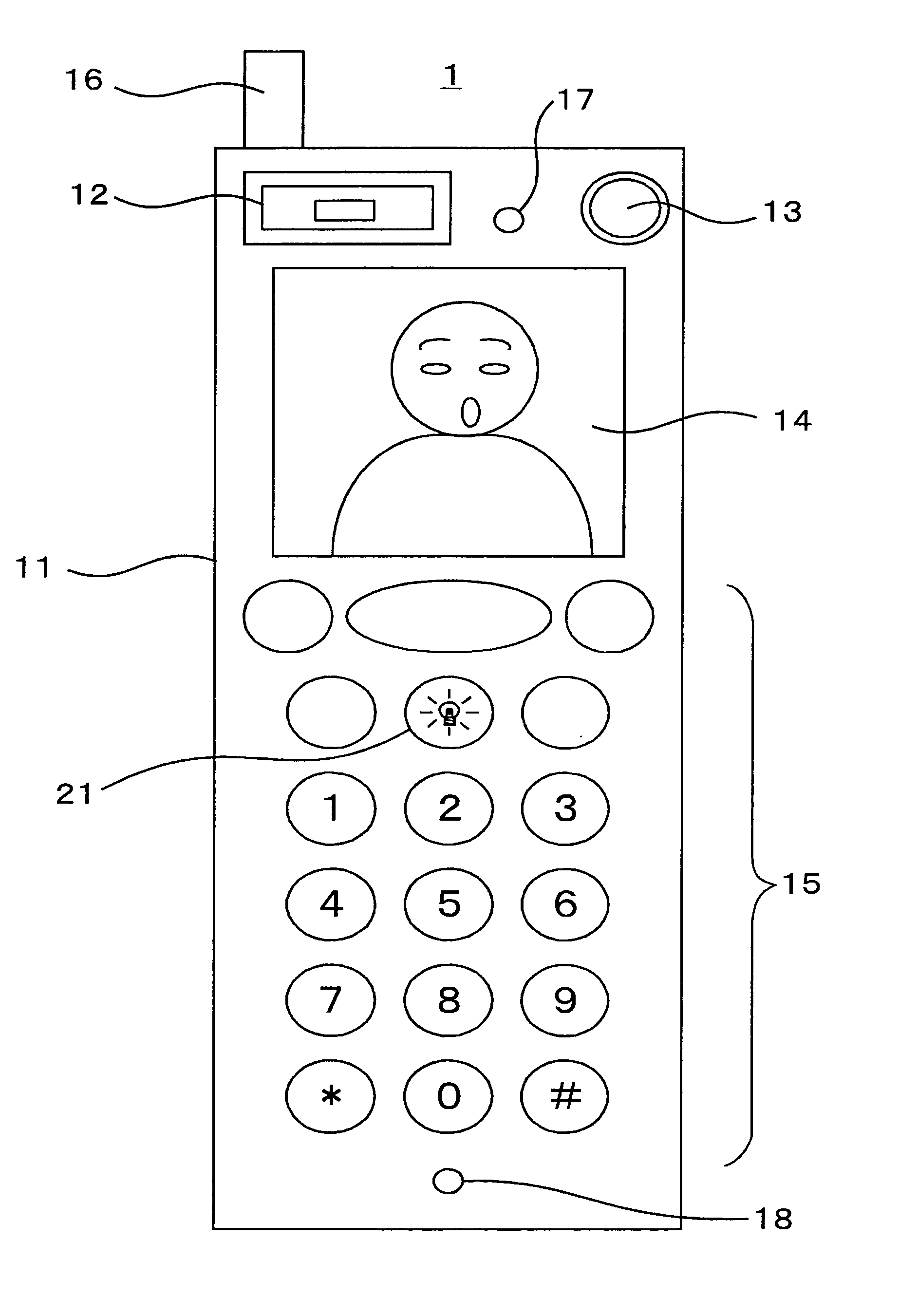
[0053]FIG. 1 shows an external view and shape of a cellular phone with a built-in camera according to a first embodiment of the present invention.

[0054] In the figure, the reference character 1 designates the whole of the cellular phone with a built-in camera (which may hereinafter be referred to as “camera-equipped cellular phone”) of the first embodiment; the reference character 11 designates a housing of the cellular phone; the reference character 12 designates a light (video light) for lighting a subject continuously by means of a light-emitting diode (LED) which emits light at a high intensity. The reference character 13 designates a camera which includes an image pickup device such as a CCD and an optical lens and can take both a still picture and a moving picture. The reference character 14 designates a rectangular display (display device) using a liquid crystal or the like, provided to display information about an operation, text information, or an image taken by the camera...

second embodiment

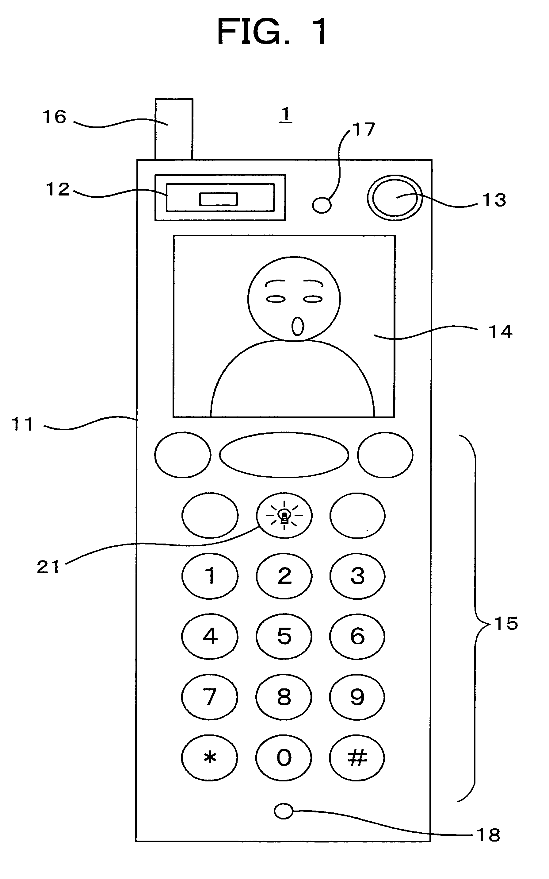
[0070] In the first embodiment described above, the light distribution lens 33 is disposed between the light-emitting diode. 32 and the transparent cover 34. A separate member, which is not shown in the figure, is required to fix the light distribution lens 33 in a prescribed position.

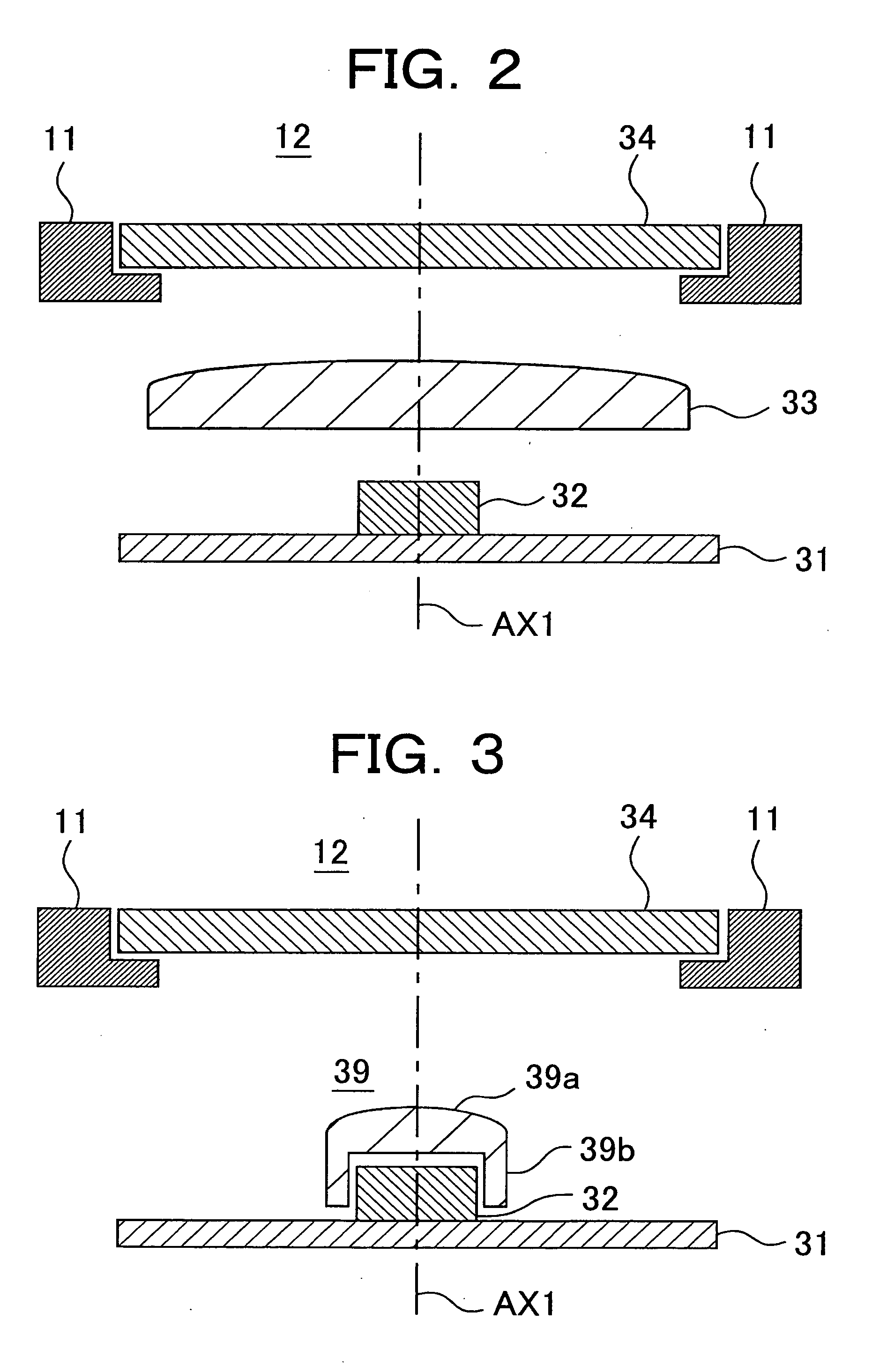
[0071] In a second embodiment described below, the need for the separate member is eliminated by fixing the light distribution lens to the light-emitting diode 32.

[0072]FIG. 3 is a cross-sectional view showing the structure of the light 12 according to the second embodiment of the present invention. The general structure of the camera-equipped cellular phone 1 of the second embodiment is as described with reference to FIG. 1, as it is in the first embodiment.

[0073] The second embodiment differs from the first embodiment in that the light distribution lens 39 of the second embodiment has a support (supporting device) 39b in the lower part (on the side of the light-emitting diode 32) of the lens porti...

third embodiment

[0075] In the first and second embodiments described above, either the light distribution lens 33 or the light distribution lens 39 is disposed between the light-emitting diode 32 and the transparent cover 34. It is required that the cellular phone accommodate the size (space), weight, and profile (thickness) of the light distribution lens 33 or 39 and the size (space), weight, and profile (thickness) of the transparent cover 34.

[0076] In a third embodiment described below, the transparent cover is formed to have a convex lens portion which has a light condensing function of a light distribution lens, eliminating the need for providing a light distribution lens.

[0077]FIG. 4 is a cross-sectional view showing the structure of the light 12 according to the third embodiment of the present invention. The general configuration of the camera-equipped cellular phone 1 of the third embodiment is as described with reference to FIG. 1, as it is in the first and second embodiments.

[0078] The...


PUM


Abstract

A light which can emit light continuously can be added to a cellular phone (1) while demands for reduction in size, weight, and thickness are being satisfied; by providing a cellular phone equipped with a camera (13) for taking a moving picture of a subject, with a lighting device (12) for illuminating a subject by means of a light-emitting diode, a switching device (21) for turning on a lighting device (12), a light distribution lens for condensing light radiated from the lighting device (12) toward the subject, and a transparent cover for protecting the light distribution lens on the subject side, which is the front side, of the lighting device (12).

Description

BACKGROUND OF THE INVENTION [0001] 1. Field of the Invention [0002] The present invention relates to cellular phones equipped with a built-in camera which takes a moving picture by means of a solid-state image sensing device, especially a cellular phone with a built-in camera having a lighting device to be used in low light such as at nighttime. [0003] 2. Description of the Related Art [0004] Recently, cellular phones with a built-in still camera have been commercially available. The sizes of image pickup devices and lenses are limited, and the dimensions of the cellular phones should not be increased, so that it has been difficult to shoot a subject under low light conditions. Known solutions that have been taken to make it possible to shoot a subject in low light are to incorporate a strobe light used for an ordinary camera into a cellular phone with a built-in still camera and to connect an external strobe light to a cellular phone with a built-in still camera. [0005] One convent...

Claims


Application Information

Patent Timeline
Patent Type & Authority Applications(United States)
IPC IPC(8): H04M1/02H04M1/22H04M1/724H04N23/75
CPCH04M1/0264H04M1/22H04N2007/145H04N5/2256H04M1/72519H04M1/724H04N23/56H04M1/00H04N23/00H04N23/75
Inventor KOMORI, NORIYUKINAKATANI, HIDEHIKOABE, ICHIHIRONAGATOSHI, YUSHIARIMAI, FUMIAKINAKAHATA, SHINSUKE
Owner MITSUBISHI ELECTRIC CORP
Learn More