Pulse arc welding control method and pulse arc welding device

Active Publication Date: 2009-06-18
PANASONIC CORP
View PDF9 Cites 27 Cited by
  • Summary
  • Abstract
  • Description
  • Claims
  • Application Information

AI Technical Summary

Benefits of technology

[0018]As still another aspect of the pulse arc welding device of the present invention, the gradient of a current waveform under a short-circuited condition is changed according to a lapse of time since the short circuit has occurred or according to output voltage. According to the control of the device, the longer the period from the moment of the short circuit, the greater the gradient of the current waveform in the short-circuited condition. The control of a waveform gra

Problems solved by technology

Such an output control of a conventional pulse arc welding device, however, has pending problems.
Such a prolonged short-circuit period in the high current region of the basic pulse inter

Method used


Image

  • Pulse arc welding control method and pulse arc welding device
  • Pulse arc welding control method and pulse arc welding device
  • Pulse arc welding control method and pulse arc welding device

Examples


first exemplary embodiment

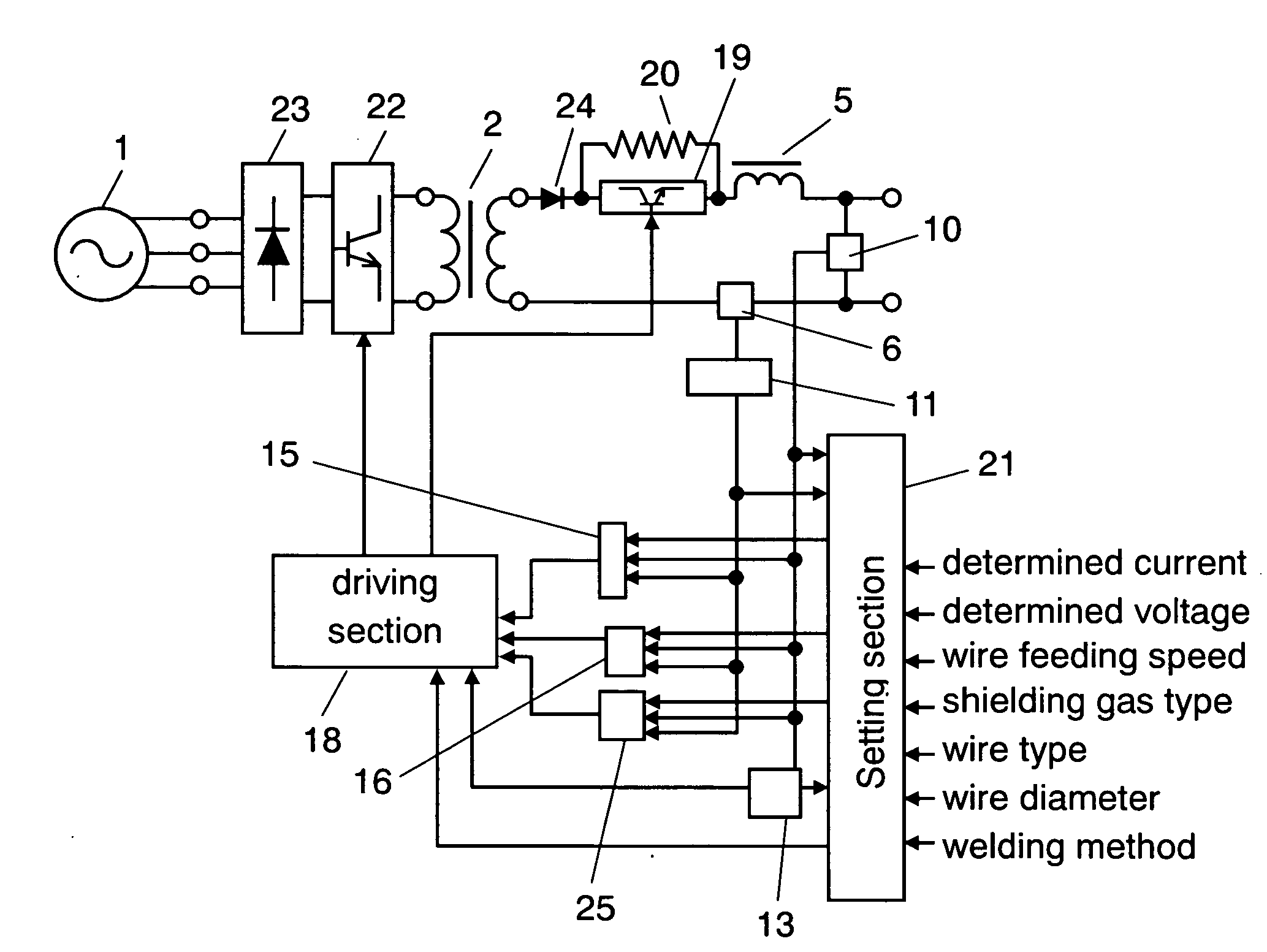
[0062]Hereinafter will be described the structure of the first exemplary embodiment with reference to FIGS. 1 and 2. In the drawings, the same parts as those shown in FIG. 4 that illustrates a control method employed for a conventional pulse arc welding device described in Background Art are designated by similar marks, and a detailed explanation thereof will be omitted.

[0063]FIG. 1 schematically shows the structure of the arc welding device of the first exemplary embodiment. In the arc welding device of the present invention, input power supply 1 is connected to primary rectifying element 23 that rectifies the output of input power supply 1. Receiving the output from primary rectifying element 23, primary switching element 22 controls welding output. Receiving the output from primary switching element 22, transformer 2 provides power conversion. Secondary rectifying element 24 rectifies the secondary output of the transformer. Secondary switching element 19 is connected in series w...

second exemplary embodiment

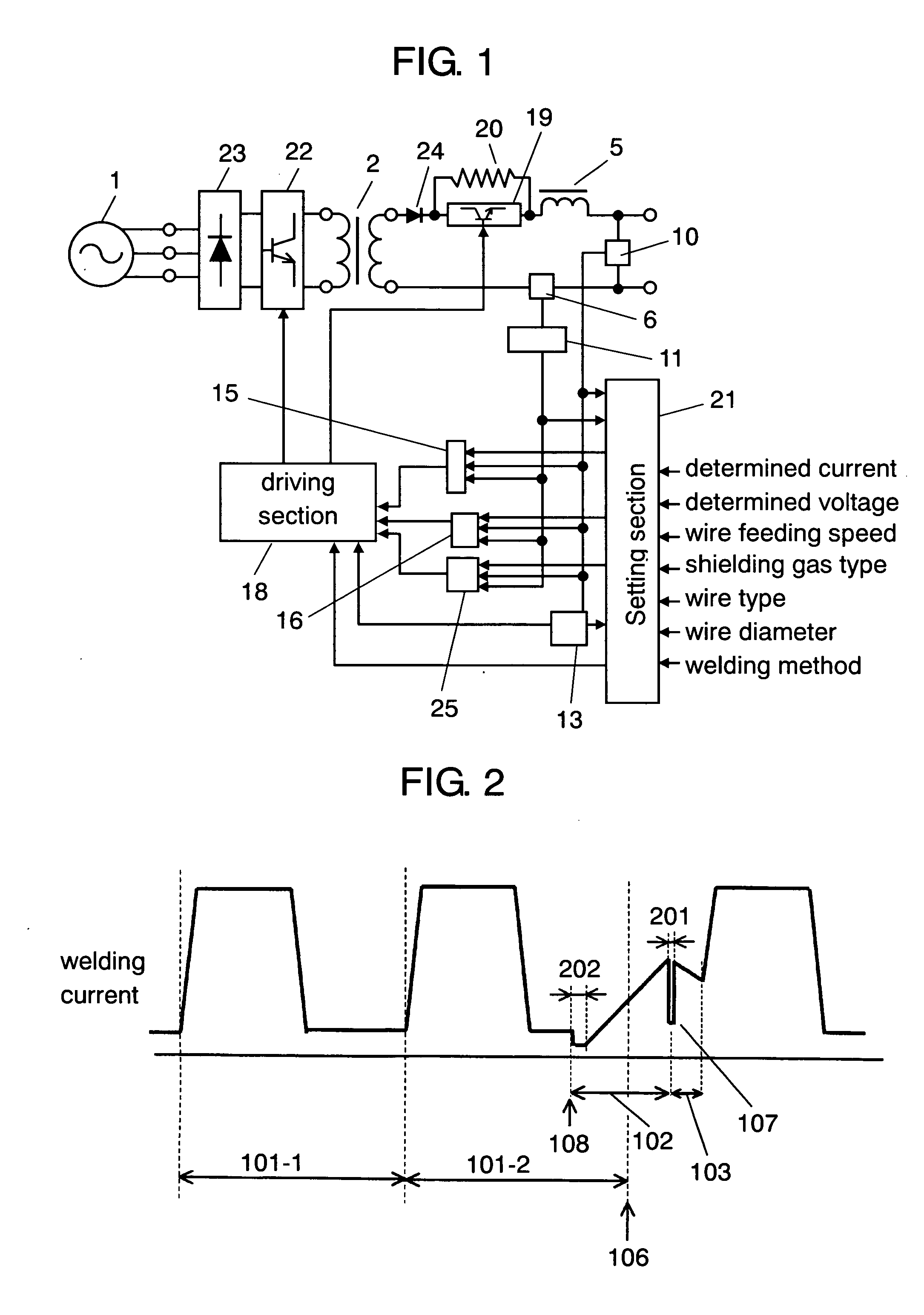
[0074]Here will be described the control method of the pulse arc welding device of the second exemplary embodiment with reference to FIG. 1 and FIG. 2. In the embodiment, the same parts as those of the structure described in the first exemplary embodiment are designated by similar marks, and a detailed explanation thereof will be omitted.

[0075]The control method of the second embodiment differs from that of the first embodiment in that secondary controller 25 controls switching element 19 so as to sharply decrease welding current not only when a short circuit is recovered but also when a short circuit occurs.

[0076]In arc welding, generally, the higher the welding current value when a short circuit occurs, the larger the amount of spatters. In the welding device of the embodiment, on detecting a short circuit, arc short-circuit judging section 13 sends a short-circuit detecting signal to setting section 21. In response to the signal, setting section 21 immediately outputs a parameter...

third exemplary embodiment

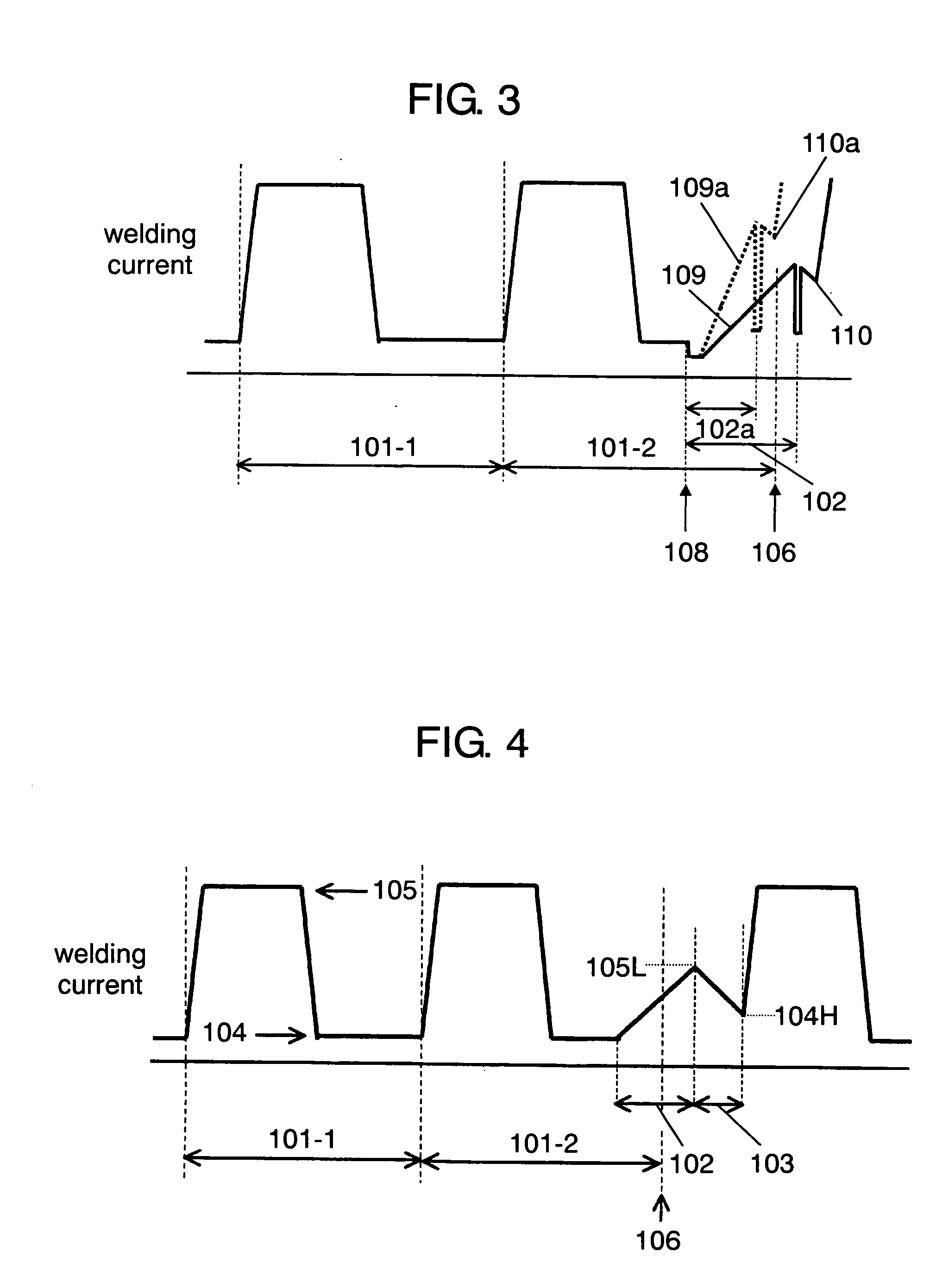
[0080]Here will be described the control method of the pulse arc welding device of the third exemplary embodiment with reference to FIG. 3. In the embodiment, the same parts as those of the structure described in the first exemplary embodiment are designated by similar marks, and a detailed explanation thereof will be omitted. The control method of the third embodiment differs from the method described in the first embodiment in that, according to the condition of a short circuit, setting section 21 changes the gradient of a waveform of current applied for recovering from a short-circuit, as shown in FIG. 3. The detailed description will be given later. The dotted lines in FIG. 3 show a case where a waveform with a steeper gradient is applied to recover from a short circuit.

[0081]Hereinafter will be described the control method of the pulse arc welding device of the embodiment. The description is firstly given on an example in which pulse rise time has a delay due to the occurrence ...


PUM

PropertyMeasurementUnit
Lengthaaaaaaaaaa
Currentaaaaaaaaaa

Abstract

Disclosed here is a pulse welding control method and a pulse arc welding device capable of improving arc stability, and decreasing the amount of spatters. The structure contains arc short-circuit judging section (13) for judging a welding state; setting section (21) for defining parameters used for a short-circuit period and an arc period; secondary control section (25); and driving section (18). Secondary control section (25) sharply decreases welding current on detecting a moment when the tip of a wire has a neck just before recovery from the short circuit, according to at least any one of outputs from a welding current value detector, a welding voltage value detector, and the setting section. Driving section (18) selects from outputs of a pulse-waveform circuit section and a dip-waveform circuit section according to the signal from the setting section and the output from the arc short-circuit section, and outputs the selected data to a switching element.

Description

TECHNICAL FIELD[0001]The present invention relates to a pulse arc welding control method capable of controlling welding output by automatically feeding a consumable electrode (hereinafter referred to as a wire) and alternately feeding peak current and base current between a wire and a welding base material (hereinafter, a base material), and also relates to a pulse arc welding device employing the method.BACKGROUND ART[0002]In the welding industry, the need for accelerating welding speed and reducing the amount of spatters has intensified in recent years. The accelerated welding speed leads to increase in the volume of production in a fixed time. Similarly, the suppressed spatters eliminate the post-welding process for removing spatters from a work, thereby increasing productivity of welding.[0003]Pulse welding output control has conventionally begun with the start of the output of pulse current. When an arc is properly provided with no short-circuit between a wire and a base metal ...

Claims


Application Information

Patent Timeline
IPC IPC(8): B23K9/10
CPCB23K9/092
Inventor KAWAMOTO, ATSUHIROMUKAI, YASUSHIKOWA, MASARU
Owner PANASONIC CORP
Why Eureka
Try Eureka