Laser-electric arc composite welding method through extra electric field

A technology of external electric field and composite welding, which is applied in the field of material processing, can solve the problems of arc electric field strength reduction, etc., and achieve the effects of improving arc stability, promoting ionization, and large welding penetration

Inactive Publication Date: 2010-06-23
DALIAN UNIV OF TECH
View PDF0 Cites 17 Cited by
  • Summary
  • Abstract
  • Description
  • Claims
  • Application Information

AI Technical Summary

Problems solved by technology

[0005] The purpose of the present invention is to solve the problem that the arc electric field intensity decreases in the laser-arc hybrid welding process, and to provide a laser-arc hybrid welding method with an applied electric field. On, to obtain greater penetration, improve welding efficiency

Method used


Image

  • Laser-electric arc composite welding method through extra electric field
  • Laser-electric arc composite welding method through extra electric field
  • Laser-electric arc composite welding method through extra electric field

Examples


Embodiment 1

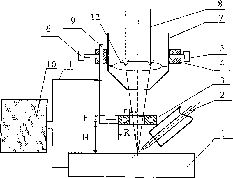
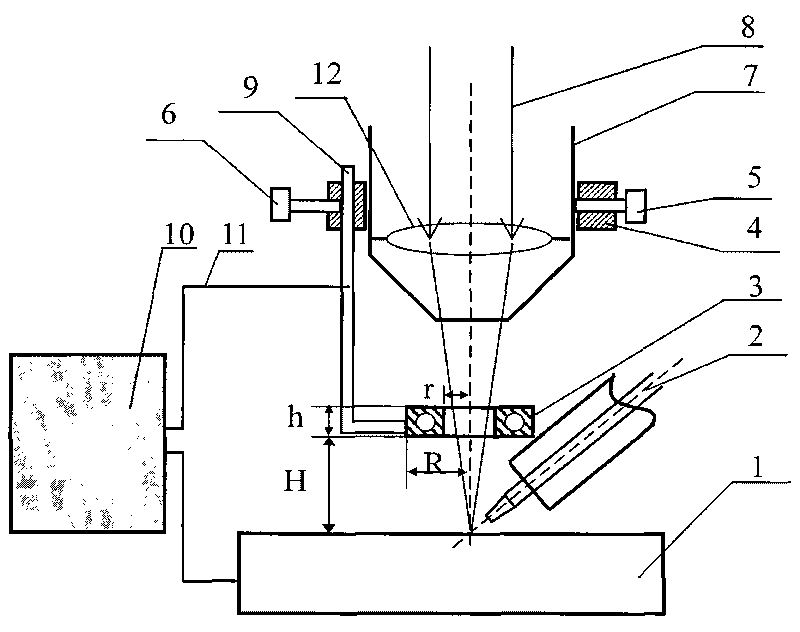
[0019] Embodiment 1, the laser-arc paraxial composite welding method with an external electric field is used to weld Q235B low carbon steel with a thickness of 1.8mm.

[0020] The welding device and the installation of the external electrode are as follows: figure 1 As shown, the laser 8 is arranged paraxially with the arc electrode 2, and the external electrode 3 is a copper alloy circulating water cooling structure with an inner diameter of the cooling water channel of 4mm, the thickness h is 6mm, the electrode radius R is 15mm, and the electrode center opening radius r is 5mm . The cooling water flow rate is 10L / min.

[0021] One end of the conductive connecting rod 9 is fixed with the external electrode 3, and the other end is installed on the fixed support 4 with the fastening screw 6, and the fixed support 4 is installed on the laser gun body 7 with the fastening screw 5, and the external electrode 3 is welded to the The height distance H between the workpieces 1 is 20...

Embodiment 2

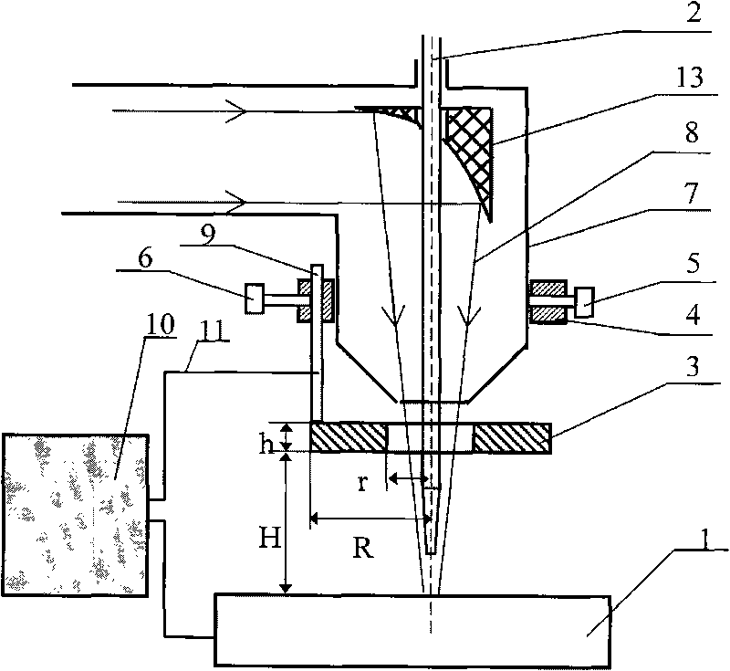
[0024] Example 2, a laser-arc coaxial hybrid welding method with an applied electric field is used to weld a 3.5 mm thick AZ31B magnesium alloy.

[0025] The welding device and the installation of the external electrode are as follows: figure 2 As shown, the height distance H between the external electrode 3 made of red copper and the workpiece 1 to be welded is 50mm, the thickness h is 8mm, the electrode radius R is 40mm, and the central hole radius r is 16mm. on workpiece 1. The installation of the external electrode 3 is the same as in the first embodiment.

[0026] Pulsed YAG laser-DC TIG arc coaxial composite welding is adopted, the average laser output power is 350W, the arc welding current is 100A, the arc voltage is 28V, the welding speed is 700mm / min, and the output voltage of DC stabilized power supply 10 is 180V.

[0027] Compared with common pulsed YAG laser-DC TIG arc coaxial hybrid welding without external electric field under the same welding parameters, the ...


PUM

PropertyMeasurementUnit
diameteraaaaaaaaaa
thicknessaaaaaaaaaa
radiusaaaaaaaaaa

Abstract

The invention belongs to the technical field of material processing, which relates to a laser-electric arc composite welding method. The method comprises the following steps: installing an extra electrode in the position with the distance of 4 to 100 mm higher from the surface of a work piece to be welded in the direction vertical to the laser beam; forming a hole in the center of the extra electrode for passing the laser beam; and respectively connecting the extra electrode and the work piece to be welded to both ends of a DC stabilized voltage supply with the output voltage between 1 and 220 V at the electric field intensity between 1 and 220 V/cm. When the laser power is between 300 W and 500 W, the electric arc current is between 100 A and 300 A, and the electric arc current is between 20 V and 35 V, the optimum range of the extra electric field intensity is between 30 V/cm and 60 V/cm. The invention can fully utilize the energy of the laser and the electric arc, and can realize the effect of obtaining large composite hot source welding fusion depth under the condition of lower laser output power. Compared with the existing laser-electric arc composite welding method under the same process condition, the invention has the advantage that the fusion depth is increased by 15 percent to 40 percent.

Description

Technical field [0001] The invention belongs to the technical field of material processing, and relates to a welding method, in particular to a laser-arc hybrid welding method. Background technique [0002] Existing studies have shown that in the process of high-power laser welding, the generated photoplasma has a shielding effect on the laser, which will affect the welding effect. The article "Research Status of Electromagnetic Field-Assisted Laser Welding" in the fifth issue of "Materials Herald" in 2009 "Pointed out that by applying an electric field and a magnetic field between the laser nozzle and the workpiece, the charged particles in the plasma can move under the action of the electric field force or Lorentz force, and their density and distribution as well as the shape and position of the plasma are uniform. Changes will occur, thereby reducing the shielding effect of the photoplasma on the laser, improving the utilization rate of laser energy, thereby improving the...

Claims


Application Information

Patent Timeline
Patent Type & Authority Applications(China)
IPC IPC(8): B23K28/02B23K26/348
Inventor 刘黎明张兆栋宋刚黄瑞生
Owner DALIAN UNIV OF TECH
Why Eureka
Try Eureka