Illuminating device and projection type video display

Inactive Publication Date: 2006-02-02
SANYO ELECTRIC CO LTD
View PDF2 Cites 45 Cited by
  • Summary
  • Abstract
  • Description
  • Claims
  • Application Information

AI Technical Summary

Benefits of technology

[0038] As described above, according to the present invention, the illuminating device has a plurality of light sources formed of one or a plurality of solid light-emitting elements, and the solid light-emitting element is allowed to emit pulses of light. Accordingly, it is possible to totally increase light amount com

Problems solved by technology

However, it appears to be a reality that a practical illuminati

Method used


Image

  • Illuminating device and projection type video display
  • Illuminating device and projection type video display
  • Illuminating device and projection type video display

Examples


Example

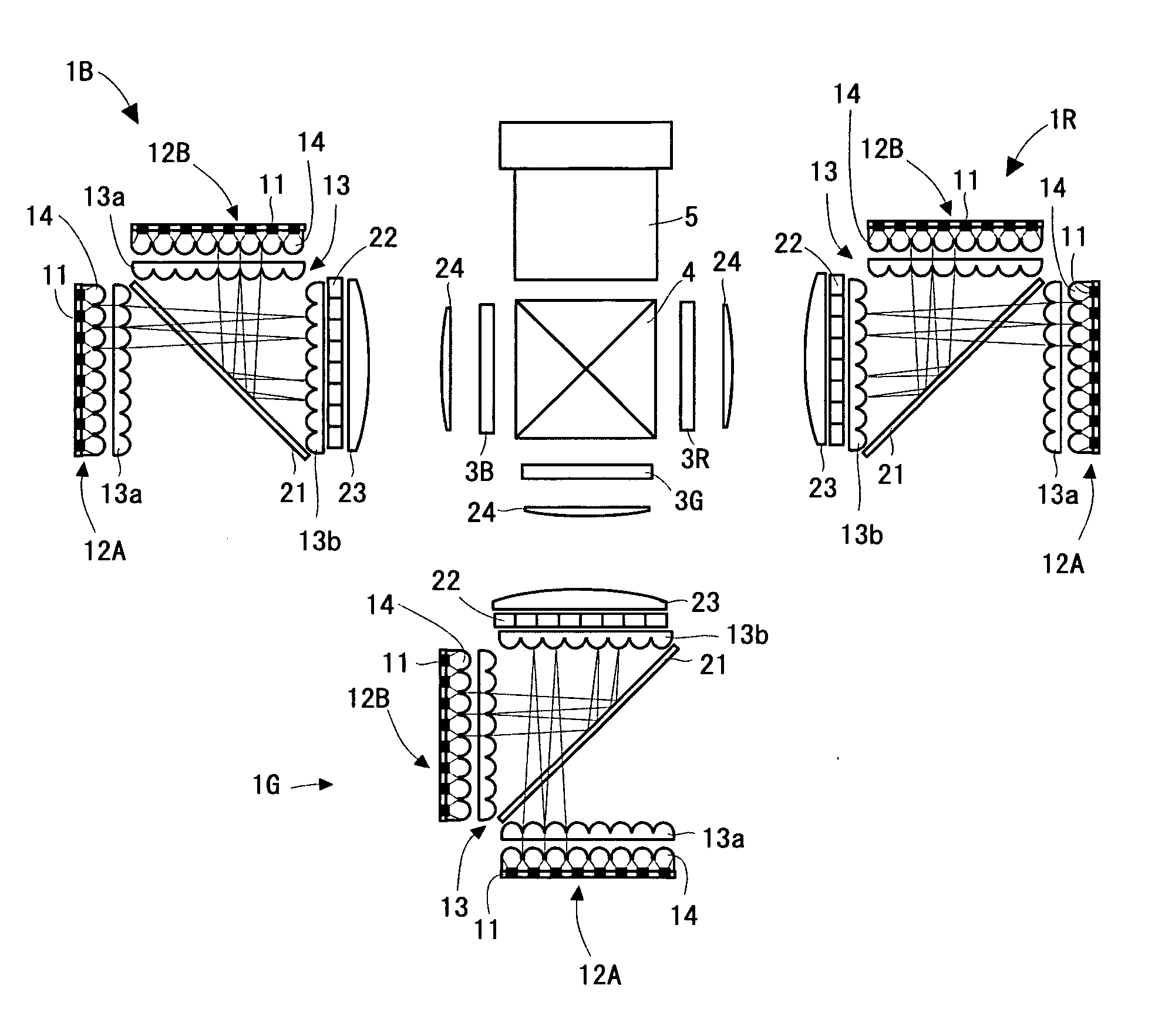
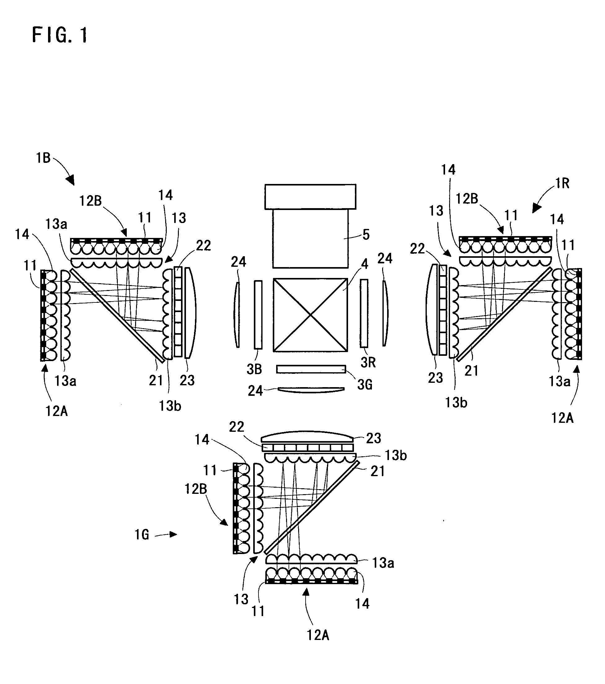
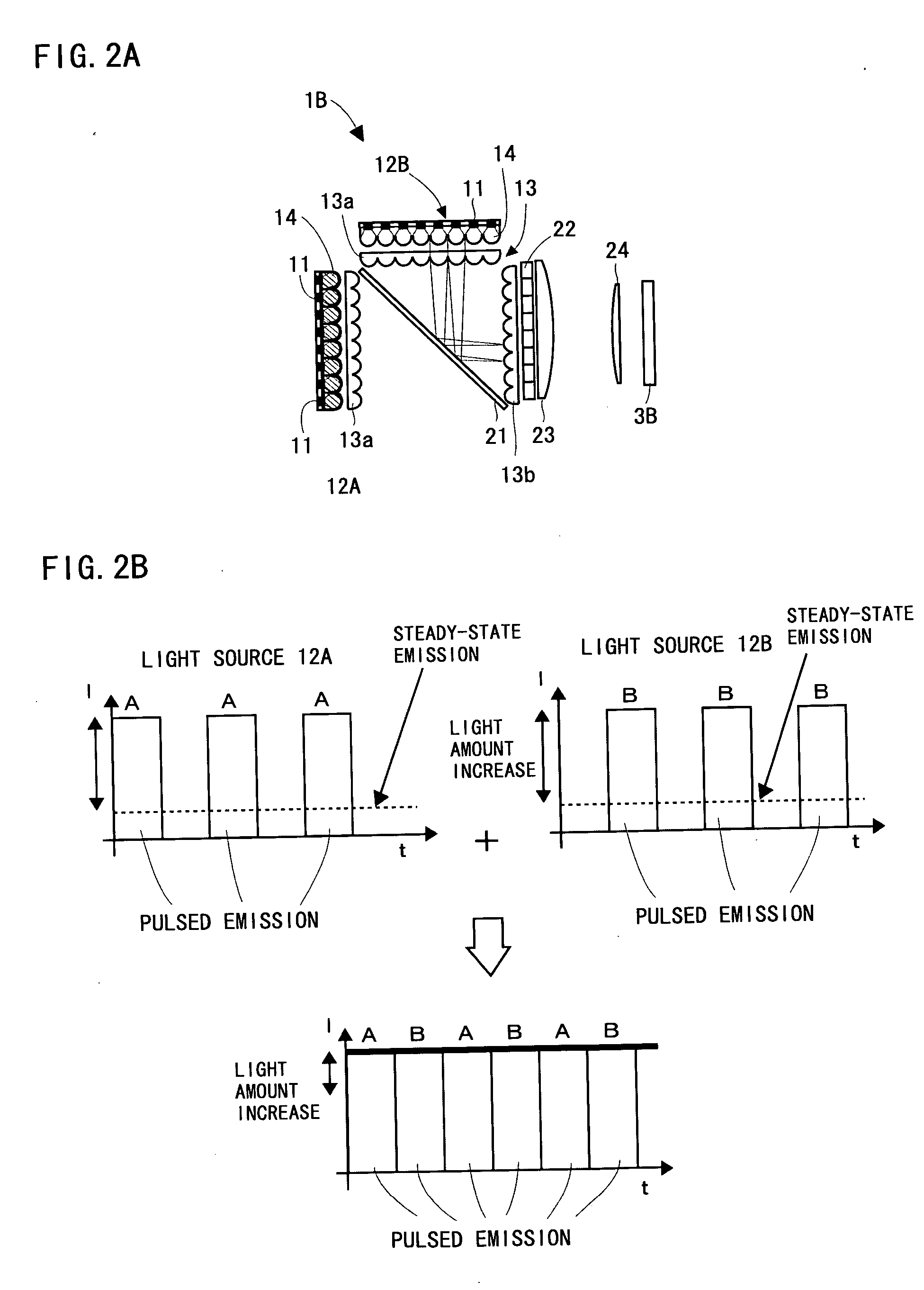
[0067] Hereinafter, a projection type video display of a first embodiment of the present invention will be described on the basis of FIGS. 1 to 11. It is noted that, in every example of the embodiment 1, light from a plurality of light sources is guided to the same optical path. However, a configuration in which a difference in wavelength of light is utilized (for example, a configuration in which a dichroic mirror, etc. are used) and a configuration in which a difference in polarization (for example, a configuration in which light is combined by utilizing transmission of P-polarized light and reflection of S-polarized light) are not adopted. That is, a configuration in which light sources that emit light of the same quality in view of color and polarization are used as respective light sources is realized.

[0068]FIG. 1 is a diagram showing an optical system of a three-panel projection type video display. The projection type video display comprises three illuminating devices 1R, 1G,...

Example

Embodiment 2

[0096] Hereinafter, an illuminating device and a projection type video display according to a second embodiment of the present invention will be described on the basis of FIGS. 12 to 22.

[0097]FIG. 12 is a descriptive diagram showing an illuminating device 100A. A first light source 102 (hereinafter, a numeral 102A is added in some cases) and a first polarization conversion system 103 (hereinafter, a numeral 103A is added in some cases) are arranged on a first light-incidence surface of a polarized light mixing element (optical path changing means) 101, and a second light source 102 (hereinafter, a numeral 102B is added in some cases) and a second polarization conversion system 103 (hereinafter, a numeral 103B is added in some cases) are arranged on a second light-incidence surface of the polarized light mixing element 101. The first light-incidence surface and the second light-incidence surface cross each other at 90 degrees. In addition, a polarized light mixing surfa...


PUM


Abstract

An illuminating device comprises a first light source in which LED chips are arranged in an array shape and a second light source in which LED chips are arranged in an array shape. The two light sources of each illuminating device are arranged such that the main light-emission optical axes of the light sources are perpendicular to each other. Moreover, a time-division switching mirror is provided at a crossing position between the main light-emission optical axes. The first light source and the second light source alternately emit pulses of light. The pulsed emission is a method of supplying a large amount of electric currents to the LED chips in a short time period, and a light-emitting amount increases compared to a steady-state emission of the LED chips. The time-division switching mirror becomes a transmitting state when the first light source is lighted, and becomes a reflecting state when the second light source is lighted.

Description

BACKGROUND OF THE INVENTION [0001] Field of the Invention [0002] The present invention relates to an illuminating device and a projection type video display. [0003] Generally, an illuminating device used for a liquid crystal projector is formed of a lamp such as an ultra-high pressure mercury lamp, a metal halide lamp, a xenon lamp, and etc., and a parabolic reflector for collimating its irradiating light. In addition, in such the illuminating device, in order to reduce a non-uniformity of a light amount on an irradiating surface, there is sometimes provided an integrating function by a pair of fly's eye lenses (referred to as a function for superimposing and converging plural illuminating areas of predetermined shape formed by sampling within a plane surface by an optical device on an object to be illuminated). Furthermore, in recent years, from the viewpoint of power saving, or others, it is attempted to use a light-emitting diode (LED) as the light source (see Japanese Patent App...

Claims


Application Information

Patent Timeline
IPC IPC(8): G03B21/26
CPCG02B27/0961G02B27/1026G02B27/1046G02B27/1086G02B19/0028G02B27/147G02B27/149G03B21/26G02B19/0066G02B27/145
Inventor IKEDA, TAKASHIYOSHII, SHOUICHIYOKOTE, YOSHIHIROMAEDA, MAKOTO
Owner SANYO ELECTRIC CO LTD
Why Eureka
Try Eureka