

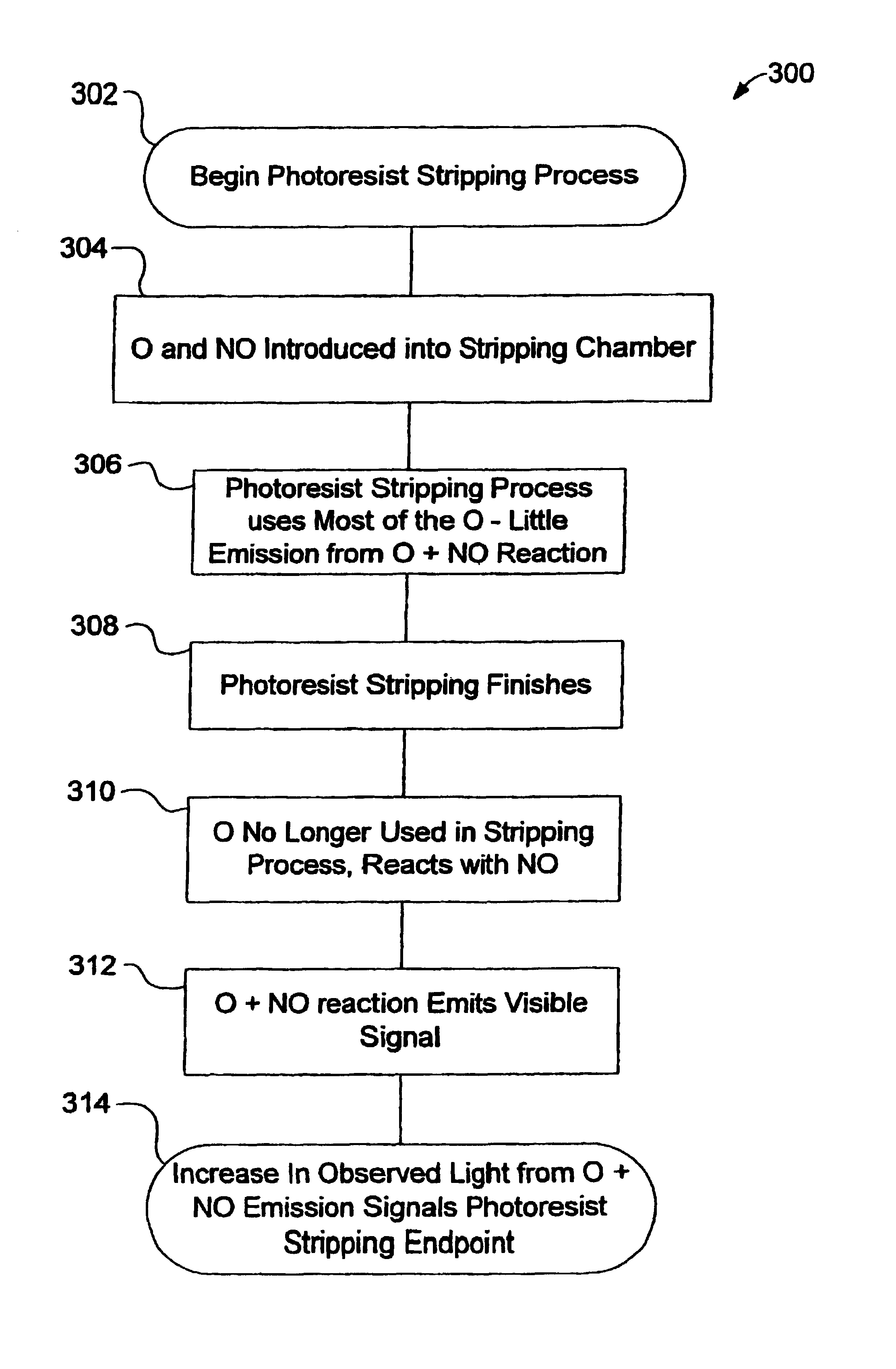
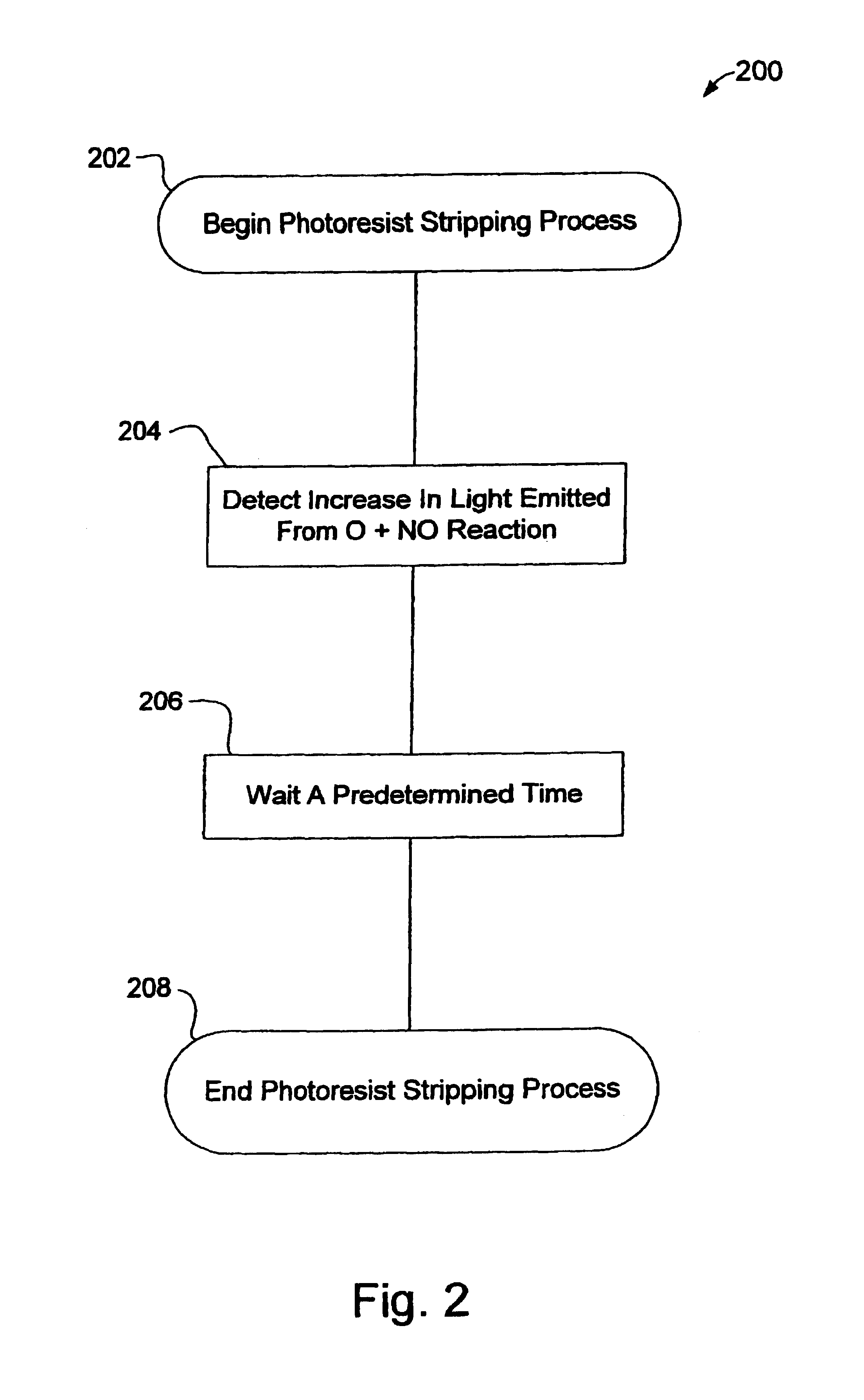
Methods for detecting the endpoint of a photoresist stripping process
- Summary
- Abstract
- Description
- Claims
- Application Information
AI Technical Summary
Benefits of technology
Problems solved by technology
Method used
Image

Examples
first embodiment
[0028]FIG. 4 is a schematic view of an apparatus 10. A plasma chamber 12 comprises an inlet 14 and an outlet 16. In a preferred embodiment, a flow of O2 and N2 enters the plasma chamber 12 through the plasma chamber inlet 14. Within the plasma chamber 12, the O2 and N2 are dissociated so that NO and O are formed. The flow of NO and O exits the plasma chamber 12 through the plasma chamber outlet 16. A stripping chamber 18 comprises an inlet 20 and an outlet 22. The plasma chamber outlet 16 is in fluid communication with the stripping chamber inlet 20. Thus, the flow of NO and O enters the stripping chamber 18 as it leaves the plasma chamber 12. Substantially no plasma enters the stripping chamber 18 from the plasma chamber 12, only uncharged gas.
[0029]A wafer 24, at least partially coated with a layer of photoresist 26, is disposed inside the stripping chamber 18. As the flow of O and NO passes through the stripping chamber 18, the O reacts with the layer of photoresist 26 and remove...
second embodiment
[0031]FIG. 5 is a schematic view of the apparatus 10. In this embodiment, a flow of O2 enters the plasma chamber 12 through the plasma chamber inlet 14. Within the plasma chamber 12, the O2 is dissociated so that O is formed. The flow of O exits the plasma chamber 12 through the plasma chamber outlet 16. The flow of O enters the stripping chamber 18 as it leaves the plasma chamber 12. Substantially no plasma enters the stripping chamber 18 from the plasma chamber 12, only uncharged gas. A separate input 40 to the stripping chamber 18 is provided to supply a flow of NO to the stripping chamber 18.
[0032]In the embodiment shown in FIG. 5, the window 30 and detecting apparatus 28 are placed close to the NO input, to aid detection of the light emitted in the reaction of O and NO. The detecting apparatus 28 detects the intensity of light emitted by the reaction of O and NO to form NO2, just as in the embodiment shown in FIG. 4.
third embodiment
[0033]FIG. 6 is a schematic view of the apparatus 10. In this embodiment, the reaction of NO and O to produce NO2 and light does not occur within the stripping chamber 18. In this embodiment, a flow of O2 enters the plasma chamber 12 and is dissociated so that a flow of O enters the stripping chamber 18, while substantially no plasma enters the stripping chamber 18. Substantially no NO exists in the stripping chamber 18, so the level of light emitted inside the stripping chamber 18 from the reaction of O and NO to form NO2 is essentially zero. As a flow of O leaves the stripping chamber 18 through the stripping chamber outlet 22, it enters a downstream channel 60. A flow of NO in introduced into the downstream channel 60 through an inlet 62 into the downstream channel 60. In the downstream channel 60, the flow of NO and the flow of O react to produce NO2 and light. This light in the downstream channel 60 is detected by the detecting apparatus 28. Preferably, the detecting apparatus ...
PUM
 Abstract
Description
Claims
Application Information